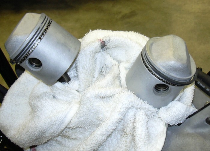
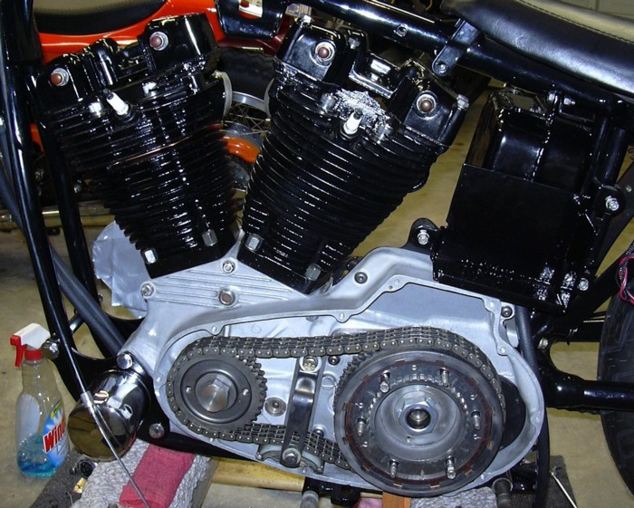
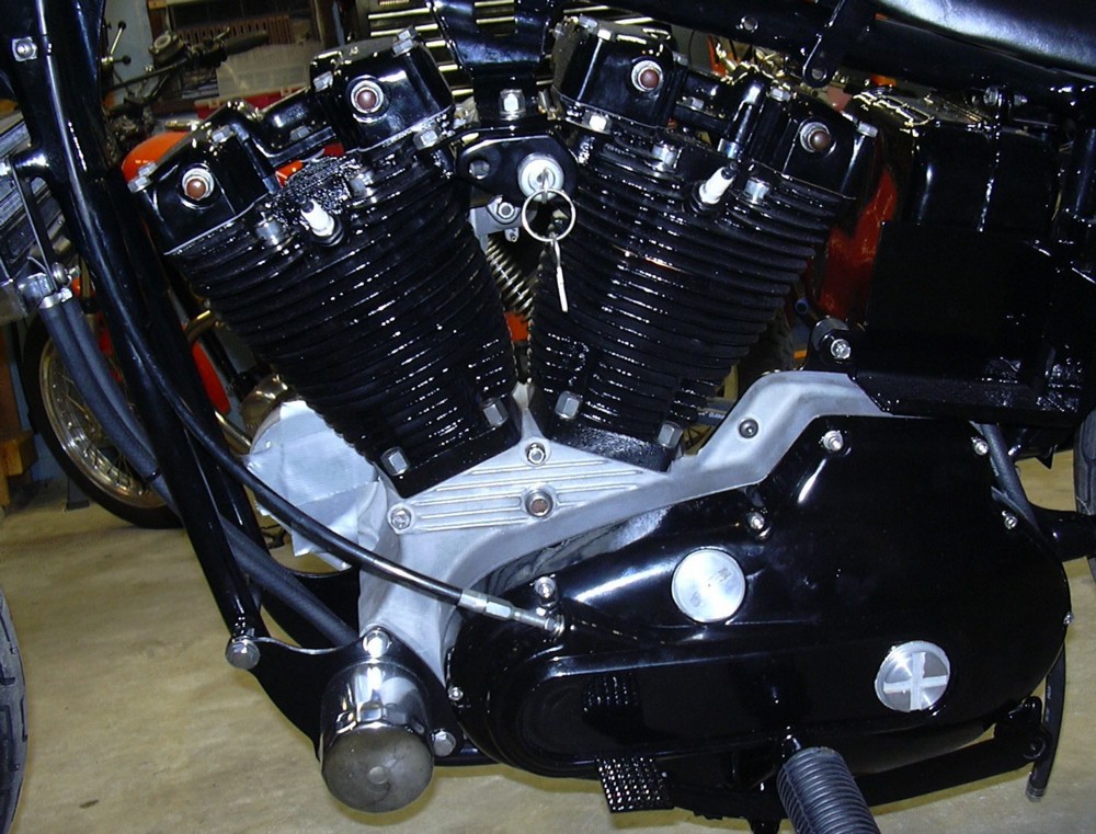
Progress to date, Tuesday, April 25, 2006. With the cases in the frame the rest of the build up consists of attending to the hundreds of little tasks that make up final assembly. I had a halfway decent set of jugs and pistons leftover from when I built my stroker, so I honed those jugs out a little and bead blasted the pistons. They are not quite as perfect as I'd like them to be, there are a few light vertical scratches on the jugs and the pistons, but I think they will work just fine. Just a note, the jugs and heads are painted, not powder coated. There is a special powder for high heat uses which I haven't used yet and I don't feel like figuring it out just quite yet. I use Plasti-Kote Engine Enamel, I've used it on a lot of engines and the stuff is incredibly durable.
See the rags jammed in around the pistons and rods? Ever drop a piston pin spiral lock ring into a crankcase? It is a lot easier to make sure you don't drop one in there than to try to fish one out. The piston and jug assembly is straight forward, lube up the piston and the jug with engine oil, remember to put the base gasket on and drop the jug over the piston. I'm not going to go into measuring jugs and pistons. Suffice it to say, the clearances need to be checked. If you don't know how to do it, make sure you have somebody you trust do it for you. I always do my own measurements. And check the ring end gap. A little too much is better than not enough, if a ring gets hot and expands and there is no room for it to expand into, it will break and tear up the jug. You can tell when that happens by the smoke and oily, greasy crud blowing out of your tail pipe.
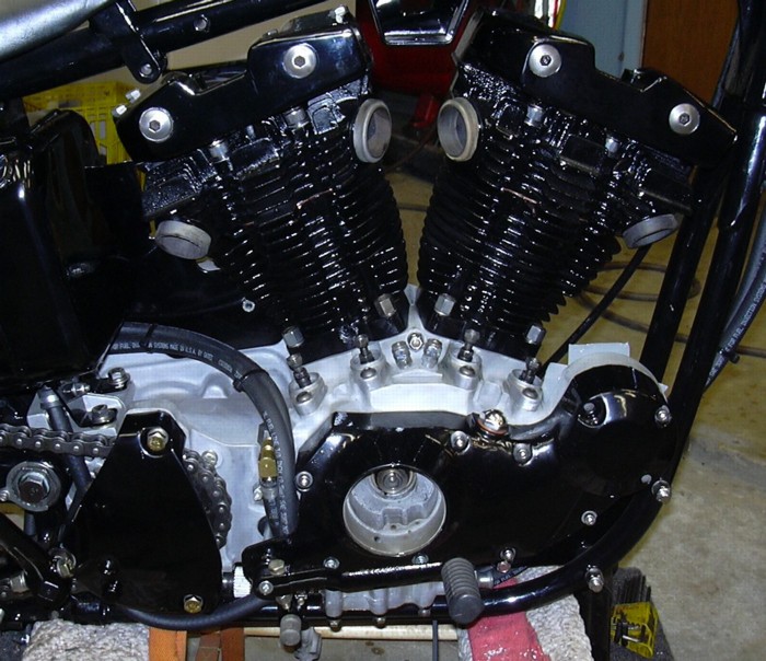
I did the heads a month ago, so they were ready to bolt on as soon as the jugs were in place. There are a couple of things to keep in mind. One of those things being the head gaskets. Most gasket kits come with a .015" thick copper head gasket, toss that one in the trash, do not use it. Order up a set of the .045" thick copper head gaskets and use those. The reason being that the spigot, that little lip that sticks up on the jug will hit the head before the head fully compresses the .015" thick gasket, the engine will probably have OK compression, but, because the copper gasket is not completely crushed, oil from the cylinder head drain back holes will be sucked into the cylinder when the pistons are moving down on the intake stroke. Don't believe me? Set the head on the jug and measure the gap between the head and the jug with a feeler gage, it will probably be about .017" or .018". You can mill or file down the spigot or you can use the thicker gasket. I like the thicker gasket, it's easier. I also like copper because it transfers heat from the head to the jug better than the fibrous gaskets. The second thing to keep in mind is that the rocker box must be bolted to the rear head before the head is bolted down. It is impossible to install the rocker box after the rear head is installed.
In my opinion the stock XL has two critical maintenance faults, one is the rear head/rocker box problem and the other is that the oil pump can't be removed without loosening all the engine mount bolts and twisting the engine around in the frame, if not removing the engine entirely.
Let's talk about head bolts for a minute, I happened to have a set of chrome socket cap head bolts, don't buy those. They suck. You can get a torque wrench on the bolts for the front head, but it is damn near impossible to get a torque wrench on the two right side bolts for the rear head, largely because the god damn rocker box that you have to bolt on before you bolt the head on, is in the god damn way. If I had a full set of stock head bolts I would have used them, but I didn't, so I used the left over chrome socket cap bolts which I took off of another engine because they sucked so bad. The stock bolts are a little easier to get torqued up.
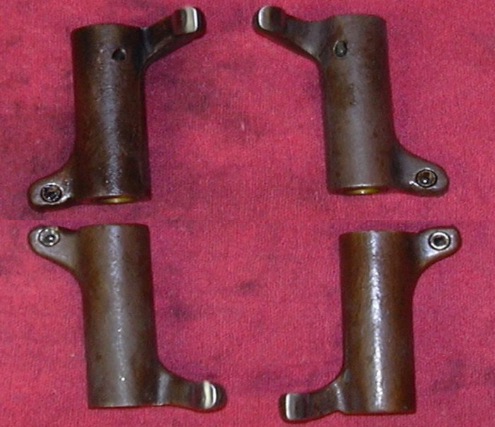
So let's talk about rocker boxes and rocker arms for a minute or two. Being old fashioned your XL has four rocker arms, they are all four different from one another, but they ain't idiot proof. The exhaust valve rocker arm has an extra hole to dump oil on the exhaust valve. It is possible to put a rear intake rocker arm on in place of the front exhaust rocker arm. So pay attention to where the extra hole is and don't screw this up. If the tip of the rocker arm that pushes the valve open is pitted or galled you can smooth it up with a sanding drum on a Dremel tool. And that wraps up the top end.
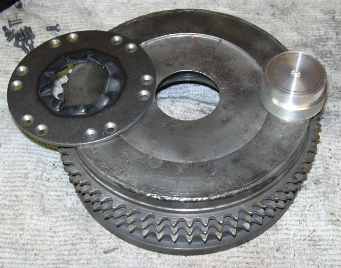
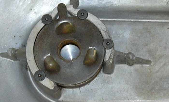
Moving on to the primary. You may have noticed me bitch back when I began this project last November that I was missing the entire primary drive. Well I've been buying bits and pieces on eBay and have most all of it rounded up. One of the things I had to do was to rivet a kick start ratchet plate to an electric start clutch basket (the eagle-eyed among you will notice the ring gear is gone, I gound the weld down and removed.) I also ended up buying the V-Twin brand kick start parts. You get a kick start shaft, ratchet plate, kick start gear, kick start shaft gear, nut and lock tab. All quality stuff, except for the way they drilled and countersunk the holes for the ratchet plate. The countersinks are way too deep, the head of the rivet is below the surface of the ratchet plate. If you leave it like that there will be a gap between the head of the rivet and the ratchet plate after you set the rivet. Believe me, I know rivets, being an ex-airplane mechanic I've driven thousands of rivets. In order to center the ratchet plate on the basket I made an alignment tool on my lathe to keep the plate centered while I drilled the rivet holes. You can pound these rivets in a number of ways, a rivet gun and bucking bar, a hammer and lump of steel, or, even a hydraulic press, which is what I used this time. All will work.
Since this was originally written I have installed many ratchet plates. I have made a few observations, and have subsequently greatly improved and refined my technique for installing the rivets.
- The rivet holes on most all clutch hubs are way bigger than the rivets that come with the ratchet plate replacement kits and the rivet will not set correctly because the hole is too big. Therefore I usually replace the standard ⅛" rivet with 5⁄32" oversized rivet. I keep a supply on hand. They usually fill the hole completely and form a nice head when they are set.
- The counter sink on every replacement ratchet plate I've ever seen does not match the countersink on the rivet so the rivet will not seat correctly in the hole when it is "set". The ratchet plate is hardened steel and can't be easily machined, therefore I have a carbide countersink tool that I use to revise the countersink so it matches the countersink on the rivets I use.
- The heads of the rivets do not sit flush with the ratchet plate, the countersinks are always too deep and the rivet head sits too low in the countersink. Therefore I have made a fixture to hold the clutch hub in alignment to a small "anvil" that fits into the countersink so that the head of the rivet will seat completely against the ratchet plate when it is "set."
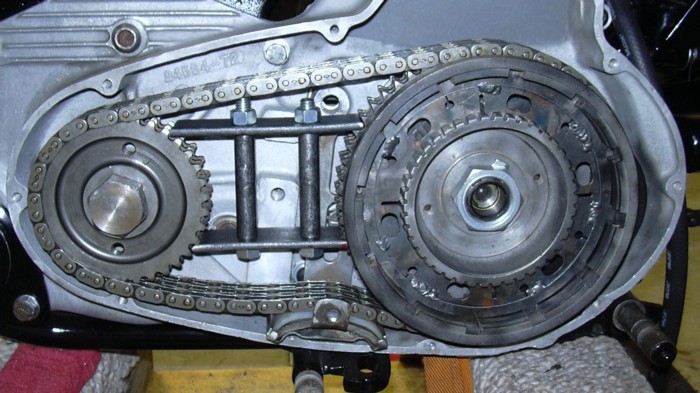
In the picture below the primary is just test fit, I found out I need a snap ring for the bearing in the clutch hub before I can actually tighten all the bolts up and install the clutch. I also had to make a spacer to get the clutch hub to line up with the motor sprocket. HD sells (actually HD doesn't sell any Ironhead parts anymore, they are listed in the original parts manuals of the day and are currently available in the aftermarket) different length spacers, I could have bought one, but it was just as easy for me to make my own. Check the alignment by snugging up the motor sprocket and laying a straight edge across it to see where it intersects with the clutch basket. Make or buy spacers to make the two things line up. If your spacer is too long, you can grind some off. But you have to be careful, if you grind too much off there won't be enough clearance between the kick start ratchet gear and the back of the clutch basket, the two things will hit each other when the engine is running and they will make a bunch of very unfriendly noises. Mostly they will be saying things like, "hey stupid, the guy on the website said you'd fuck this up if you ground too much off." One other note here, the kick start shaft gear has a cam on it that retracts the ratchet gear when the kick start lever is up. The kick start ratchet gear rotates around the clutch spacer. If the bushing in the kick start ratchet gear is worn, the ratchet gear will sit cockeyed on the clutch spacer when it is being retracted by the cam on the kick start shaft gear, this will also allow the kick start gear ratchet gear to hit the clutch hub when the engine is running. I had a whole box of kick start parts and was originally planning to go through that stuff and pick out the best of it and use it rather than buy new parts, but when I sat down and started matching up spacers to bushings to gears I found out I didn't have the right combination of spacers the correct length that weren't worn too bad to use to go with gears that had good bushings in them. So that is when I decided to use the V-Twin stuff. One other point to mention, the early XL's kick start ratchets, and I'm not sure where the change over is, had more ratchet teeth on them, so you cannot mix an early style ratchet plate with a late style ratchet gear. You can convert the early style to the later style, as a matter of fact you pretty much have to because the early style parts are not available from HD or aftermarket (since this was originally written I have found that all versions are available in the aftermarket.)
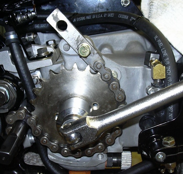
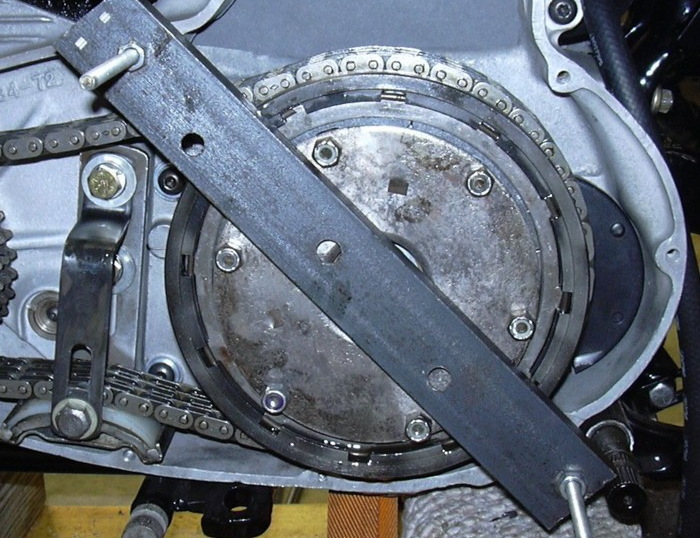
Moving over to the other side of the bike, here is a handy dandy little tool. Just the thing you need to hold a sprocket when it is time to tighten the big nut. Just a piece of old chain and a piece of steel bar. Find something sturdy on the bike to bolt the steel bar to. Be careful, if you don't find something sturdy enough, you can break a chunk off the bike. On Sportsters I use one of the sprocket cover mounting bolt holes. This tool works on big twins too, it even works on my Yamaha, basically anything with a 530 chain. Notice the oil line routing, the line to the rear (left) of the sprocket is the feed line to the pump, notice the clamp above and to the left of the sprocket, that clamp ensures the line won't be sawed in two by the chain. The feed line is as short and as straight as possible with no elbows, I know for fact that extra elbows or bends in the feed line can cause cavitation in the oil pump. The lines to the right of the sprocket are the crankcase vent line that equalizes pressure between the crankcase and the oil tank and the return line which runs down from the brass fitting then forward to the filter and cooler before heading back to the tank.
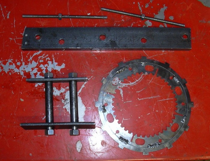
Progress to date, Sunday, April 30, 2006. Time to put the primary together for keeps. I got the snap ring for the basket bearing, everything has been test fit, tranny works good, kick start works good and all the little bits and pieces have been rounded up. Let's take a look at some handmade tools that come in handy when working on the primary. At the top is a hunk of steel channel and a couple of pieces of threaded rod. That is the clutch spring compressor. It ain't fancy but it works. On the lower left is a gadget used to lock the clutch basket to the motor sprocket so you can tighten the big nut on the motor sprocket, nothing more than some 3⁄16" steel strap, some threaded rod and a couple of pieces of steel tube, also simple and effective. And finally, two clutch disks welded together, this locks the clutch hub to the clutch basket, so you can tighten the big nut on the clutch hub. You guessed it simple and effective too.
Both locking devices installed, the front sprocket is locked to the clutch basket and the clutch basket is locked to the clutch hub. Get your big breaker bar and your big sockets out and tighten the sprocket nut and the clutch hub nut. A punch and hammer ain't going to cut it. Buy sockets that fit.
Clutch spring compressor installed. Screw the threaded rods into the appropriate primary cover screws, stuff the plates, spring and releasing disk into the basket, drop the steel bar over the threaded rods and run the nuts down. Wiggle the basket around to line up with the clutch studs and tighten the nuts. Piece of cake if you have 3 arms, otherwise a Chinese fire drill...
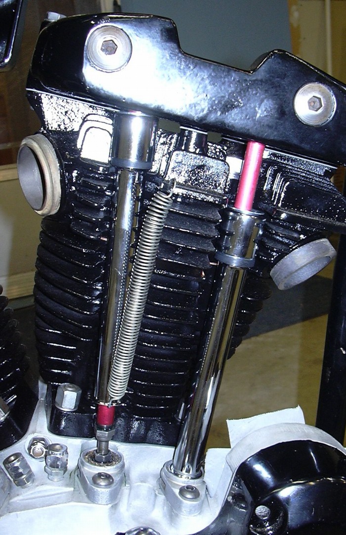
That was easy, wasn't it. So with the primary together it is time to install the push rods and adjust the valves.
Get yourself a spring to hold up the push rod covers while you are adjusting the valves, it makes it a whole bunch easier.
Time to tend to the steaks and refill my gin. Ahh, much better. Actually it is time to go eat the steaks... and have another gin. It doesn't get much better than this, perfect weather, some steaks cooking on the grill, a day spent working on a Sportster and a gin and tonic to finish the day off. Well the sun is setting on another glorious day, springtime in Texas is nice.
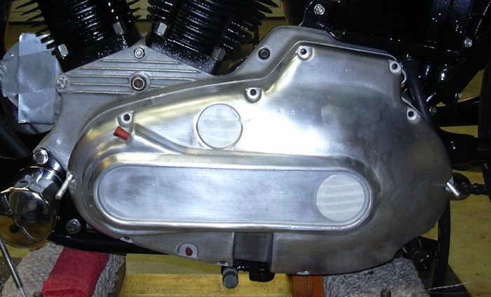
Now, primary covers and what makes me different than most guys. The primary cover on this bike is halfway trashed, I've seen worse, but I've also seen much better. The fact of the matter is that the average Joe would wipe the lumpy crud off of this one and have it bolted on in about five minutes. I'll probably have 6 hours in this cover before it is installed. First off, I sandblasted it, then spent an hour wet sanding it to get the worst of the scratches and pits out prior to powder coating it. Then I like to spot face all the bolt holes so each screw has a nice flat area to seat against. I spot faced the cam cover bolt holes too. Then I had to heli-coil where the adjuster screws into the cover. The other thing I like to do is to drill out the release ramp and drill and tap holes for 8-32 countersunk screws to hold down the release ramp, do you have to do that? No. It's just something I like to do. I would have had it powder coated, but I ran out of black powder.
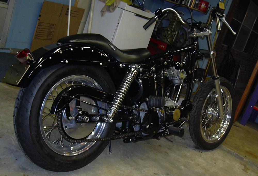
So where am I? The engine is pretty much done. The valves are adjusted, the primary cover can be installed after it is powder coated. I just bolted on an eBay carb I bought for 40 bucks, I did pull the bowl and check it out, it looked OK, we'll see how good it works in a few weeks. Oil system hooked up, even has oil pressure. I have a clutch cable and lever. I have brakes. I just drug out a set of beat up old drag pipes I plan on using, I don't like to spend any money on an exhaust. I tend to beat up an exhaust system pretty good, what with dragging the pipes on the ground while cornering at 95 MPH. It just ain't worth spending the money. This baby is getting close to fire up time. I still have to make up my mind on an ignition system, I have a coil and three sets of points cams, I think they might all be bent a little. I also have an electronic ignition module off my 93 that I think will work. Let's see, I need a headlight, gas tank, ignition, exhaust and wiring. I definitely see light at the end of the tunnel.
Progress to date, Tuesday, May 2, 2006. More black powder came yesterday. I powder coated the primary, top motor mounts, brake pedal, foot peg mounts, foot pegs, kickstand, ignition key/switch mount and some other little stuff. I spent the day bolting things together. I did have to heat the kickstand up red hot to straighten it out before powder coating it. I also made the kickstand pivot pin on my lathe because I didn't have one laying around. Pegs are on, brake pedal is on, primary is on, kickstand is on. I guess I can take the bike down off the dolly I've been rolling it around on. So I did. Now to sit on it for the first time. Uh-oh. A problem. The rear shocks springs are way too mushy, how can that be? A buddy of mine had the same problem with some late model shocks on his old Ironhead. I swapped out his mushy springs for some stiffer springs I had laying around. But I ain't got no more springs. Hey Jim, you owe me a set of springs. But this is the kind of problem that you have to expect. Still, the bike rolls on its own two wheels. A big day, definitely cause to drink a couple of gins.
As this project races??? to its inevitable conclusion, allow me to expound on Sportsters for a bit. To me the Iron XL will always be Harley's best bike. It handled better than anything else of similar displacement. Despite the smaller engine size the 900cc XLs would kill any big twin of its day. This is the bike grown men feared, it would throw you over the handlebars in a second if you didn't know what you were doing while kick starting it. But, in capable hands, this machine tore up everything put in its way, at least through the sixties. And with a little tweaking it still can put on a respectable show today. Fear No Evo, my 74 stroker literally shakes the house when I start it up in the garage, it does 70 to 120 in the blink of an eye. Men feared it for other reasons too; did your daughter ever date a guy who rode an iron XL? I bet you didn't like it, if she did. I've literally had people roll up their car windows and advert gazing on the iron beast and its rider when I've pulled up along side. How often does your mere method of transportation strike fear into the general public? Pretty often if you ride an unmuffled XL stroker I can assure you. And I wouldn't have it any other way. Look at the early XLs, Harley didn't give a damn how they looked, rough castings, raw machinery. Yet the brake pedal followed the curve of the primary perfectly. The tiny gas tank sits on top of the relatively huge engine like it belongs there. Somehow the curves of the buckhorn handlebars match the bike. Industrial design at its best. If you didn't know a damn thing about engines you could probably figure out how an XL worked. Nothing was hidden, the bits and pieces of the machine were hanging out there, exposed for all to see. Even the new ones carry that heritage. Where did it start for me? Back in high school I used to walk down to Illinois Harley Davidson and generally irritate everybody in there. I had no money and obviously I wasn't about to buy a bike. One day a guy pulled up on a purple XLCH chopper, unable to find neutral, he dropped the clutch to kill the engine. Seemingly, the back tire spun around three times before the engine quit. I knew then I had, and I mean had, to have one of those. Maybe I'll build one someday. I've probably owned 20 iron XLs over the years and I loved them all. I love this one already.
Progress to date, Friday, May 5, 2006. I needed to figure out the ignition system before moving on. I've got a late model coil and ignition module, I don't have an extra late model pickup. I also have three sets of old point cams laying around. No matter which way I go, I'm going to have to buy something. I can't use the late model electronic ignition module and coil unless I buy a pickup. I can't use the points unless I buy another coil because the point type coils have more resistance than the electronic ignition coils. The electronic ignition would be trick on this old bike, but finding somewhere to mount the module will be a problem, there ain't much extra room an an XL. So I decided to figure out a way to check the run out on the point cams, if I have a good point cam, I'll go with the points, the wiring and installation will be easier. Plus I am not sure how happy an old engine will be running with a late model XL advance curve.
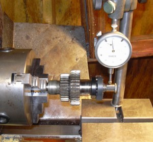
Point cam run out and why it matters. If your point cam is bent you will not be able to adjust the point gap or set the timing correctly. The point gap, when measured on the wide lobe might be OK, but when measured on the narrow lobe, might be off by several thousandths. I bolted the first old point cam to an extra number 2 camshaft I had laying around and then chucked it up in my lathe. Using a dial indicator I could tell that the high spot on the wide lobe was .005" more than the high spot on the narrow lobe. If this point cam was installed in an engine, you could set the gap on the wide lobe to .015" but then the gap on the narrow lobe would only be .010". You'd never get this engine to run right. Now, to further complicate the situation, factor in worn cam bushings. Remember back when I was installing new cam bushings in the cam cover and commented that the new bushings had several thousandths of an inch less clearance than the old ones? Since the point cam is bolted to the number two camshaft you will not be able to get a consistent point gap setting, if the cam is swimming around in a worn bushing. This will also make tuning the engine difficult if not impossible. The second point cam I checked only had .001" thou different between the narrow lobe and the wide lobe.
So now I know I have a good point cam, I have a good set of points and I have a point backing plate. All I need for the ignition is a points type ignition coil. Next step is to sit down with the catalogs and order a bunch more stuff. I decided to get a new gas tank, I've got a couple old ones I can use, but, I'd have to strip the paint off one and that is a pain in the ass and I want to powder coat the tank black. Somehow baking a used gas tank in an oven at 400 degrees for 20 minutes sounds like one stupid idea I'll be glad to say I didn't try. A new tank is "only" $120.00 bucks. The shopping lists are getting shorter, but still, there a bunch of parts to be had yet, coil, gas tank, petcock, front brake lines, air cleaner.
Progress to date, Monday, May 15, 2006. A big ol' box from J&P came a couple of days ago, tune into chapter 7 to see what happens...