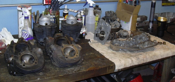
Progress to date, Sunday, March 26, 2006. I took a little break for a couple of weeks, so it was time to go back to work. Where to begin again, the workbench is much cleared off without that engine sitting there. It's been there for two years or so. I was beginning to think that it would never be moved off. So what do we have? Trans? Cam cover? Barrels? Heads? Let's work a little of all of it.
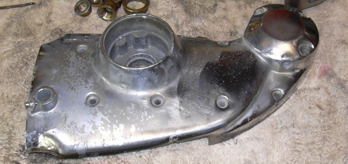
Let's start with the cam cover. It is a beat to shit, nicked up, scratched, peeling chrome with all the bushings pulled out hunk of scrap. I pulled the bushings out because I was going to send it off and have the chrome plate unplated. Then I decided it wasn't worth spending the money on. I'm really beginning to hate chrome, it is not particularly durable, when applied over steel it eventually rusts, when applied over aluminum it eventually peals off, but not completely off, just enough of it peels off so that whatever it is on looks like shit and of course the chrome that hasn't peeled off is virtually impossible to remove. I've bead blasted, wire brushed and sanded this cover to try to give it a uniform finish for powder coating and, of course, I can't get all the god damn chrome off. So I've decided to cut the cover down, less pitted peeling chrome to deal with, plus I like the way the cut covers look, and cutting the cover is the only way to get to the crankcase vent line fitting for the hose that runs to the oil tank. I use a regular old coping saw to do the cutting, then a bunch of filing and sanding. When you cut the cover down you end up cutting through the oil passage that feeds the crank and rocker arms, I drill and tap the opening for a plug, it's a handy place to plug a pressure gage in or to just check oil flow by pulling the plug out. The finished product is far from perfect, but a nice thick layer of black powder will help hide a lot of defects. While I had the coping saw out I decided to cut down the sprocket cover a little, I'm still debating as to whether I want to drill a bunch of holes in it.
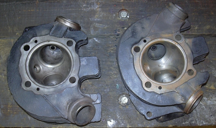
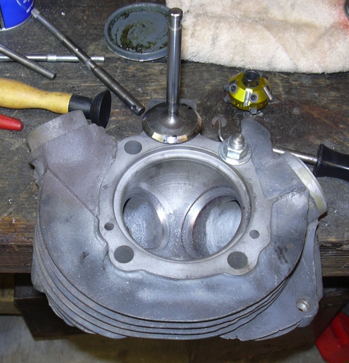
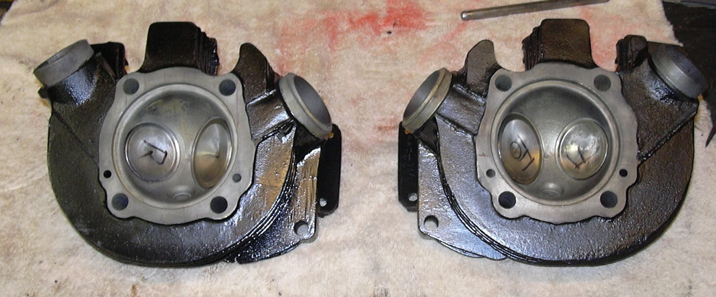
How about a little head work? I had narrowed down the choices to two sets. One set was the set I had been saving as spares for my stroker. The other set was of unknown origin. As it turns out the unknown origin set looks like they had some porting work done, it also looks like they had been welded, so I decided not to use them. But... They still had valves in them so I decided to pull the valves out and see what they looked like. Have you ever had one of those days when everything you touched turned to shit? How about, have you ever had one of those days when you take apart a set of old heads and find out they have a perfectly good set of Manley stainless steel valves in them? I've had a lot more of the former and precious few of the latter, but I'll take em when I can get em. So I've been spared a trip to the box-o-old valves or another 150 bucks worth of parts ordering.
After getting whacked 400 bucks for a valve job a few years back, I decided to buy my own valve job stuff. I had originally intended to buy a used Sioux valve grinder and seat grinder. Guess what, that shit's expensive. So I ended up buying a Neway valve face cutter and Neway valve seat cutters. As I seem to recall the whole setup put me back about 600 bucks. Still expensive, but, they have more than paid for themselves. I'd hate to do a 4 valve per cylinder V-8 with them, but they are perfect for motorcycle work.
Some words about valve jobs. I've had auto machine shops do valve jobs for me, they tend to be cheap but they only cut one angle. I've had some good valve jobs done buy some shops, they can be good, but they are always expensive. So I do my own. That way I have complete control. I always cut three angles, you want the valve to contact the seat in the middle third of the valve face, the only way to do that is by cutting three angles. So start by cleaning up the faces, the Neway cutter clamps in a vise, you rotate the cutter by hand and if you watch carefully you can see little curls of metal spinning off as you turn the cutter, it works great.
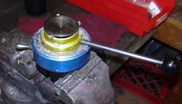
I check the valve contact with the seat by making three little stripes across the face of the valve with a magic marker, I put the valve in the guide and rotate it back and forth about 10 - 20 degrees then take the valve out and look at the little stripes, the magic marker ink is rubbed off where the seat and valve make contact. In the picture to the right, the shiny spot is where the black magic marker ink has been rubbed off, right in the middle of the valve face. A perfect contact area. If the contact is too close the edge of the valve, you use a 30 degree cutter to lower it. Too close to the bottom, you may need to make the seat a little bigger, then use the 60 degree cutter to raise the contact area. The yellow anodized thing to the right of the valve is the Neway seat cutter, it drops over a pilot inserted into the valve guide and you rotate it with a speed handle, it works great too. A little hand lapping and the valve is ready to go. You can also see my poor mans head holding fixture, that would be a workbench with a hole drilled in it, through which you insert a threaded rod to clamp the head down.
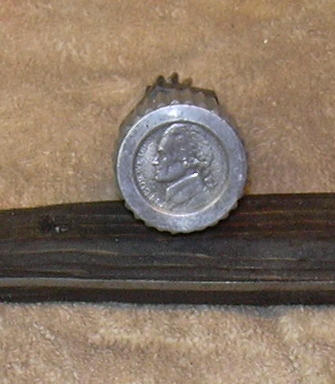
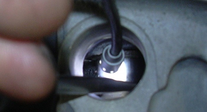
This bike will always be worth a nickel at least. How so you may ask? I used a nickel to plug the speedo drive. I don't intend on using the speedo and the drives tend to leak. So, grind a nickel down a little, back it up with a homemade gasket and cover the drive adapter on the bottom of the trans. Somebody probably makes a plug for this hole, but, I bet the plug costs more than a nickel. Why do this now? Well it was laying on my bench and needed to be done sooner or later.
Progress to date, Sunday, April 2, 2006. Well I can't get my god damn wireless router to work. Wait.. wrong subject. Oh yeah, this is about Sportsters. The last few days have been somewhat low key, with the engine in the frame, it has the feeling of being over the hump so to speak. Fitting the rear fender turned out to be a bitch as was building the front wheel brake set-up. The rest should be easy. I know I've just screwed myself by saying that. In any case, I ordered a bunch of parts, bearings and bushings for the cam cover, bearings and gears for the trans. That should keep me busy when it all gets here. Anyway, I've set down in front of the trans parts and looked it all over real good have figured out what I need, the clutch gear is no good and the main shaft third gear looks pretty beat. Other than that I am in pretty good shape in the trans. I had two main shafts, one was good. The counter shaft looked good. I actually had a sealed bearing for the trap door that was good. I also had three that were no good, I finally trashed them all. A word on those sealed bearings, even though they are sealed, crud occasionally makes it's way into one. I have popped the seal out (it can't be popped back in) and cleaned them out, they have worked fine, even without the seal. I'm not sure why exactly they are sealed, well, yeah, the obvious is true, to keep crud out. But none of the other trans bearings are sealed. If you run a magnetic drain plug to latch on to the chunks and change the primary juice halfway often, the bearing without the seal should be fine.
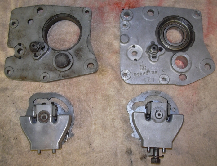
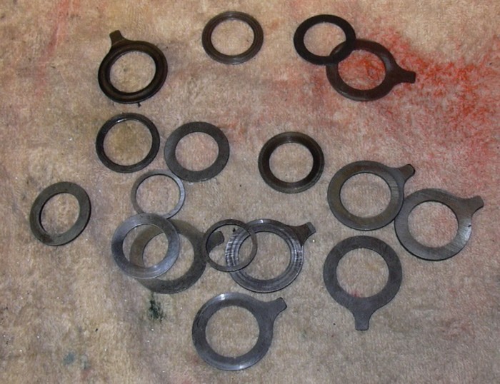
And now a training point on tranny trap doors (see the picture). The one on the right is for right side shifts, the one on the left is for left side shifts. They are basically the same, except that the one for left side shift has a cut out for the shift lever to pass through on its way out the primary cover. You can use the left side shift trap door on a right side shift bike with no changes, It looks to me that you can use the right side shift trap door on a left side shift bike, if you machine out the cut out for the shift lever. And a similar training point on the pawl carrier and shifter pawl. Notice the shifter pawl on the right, it is for a right side shift bike. You can tell because the shaft for the shifter cam extends past the top surface of the pawl carrier. The pawl carrier on the left is for the left side shift bike, you can tell because the shaft for the shifter cam is flush with the pawl carrier surface. This is so that it will clear the shifter shaft as it crosses back across to the left side of the bike on its way through the primary cover. I do believe you can use a left side shift pawl carrier on a right side shift bike. You cannot use a right side shift pawl carrier on a left side shift bike because the shifter cam shaft will hit the shifter shaft as it crosses back across to the left side of the bike on its way through the primary cover.
A final note on the trap doors, when you press the clutch hub bearing in, put the outer snap ring in and press the bearing from the inside of the door to the outside and let it bottom against the snap ring. Why? Because there is some clearance between the bearing and the snap rings. If the bearing is pressed against the inner snap ring and it looses up and moves towards the outer snap ring it will screw up the end play on your main shaft. Which might make for hard shifts or popping out of gear. I've seen it happen. With the bearing pressed against the outer snap ring you can never get too much end play because the bearing is already moved as far as it can go.
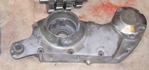
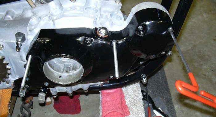
A little powder coating. I powder coated a few parts, the old battery tray, the starter bendix blanking plate, sprocket cover and cam cover. I wasn't real happy with the results of the cam cover, and I didn't think I was going to be. The pitted, flaking chrome was not a good base for the powder. But, I'm going to live with it. As flaws in fine leather, not really a defect, but proof the product is genuine. The cover is just loosely screwed on, I wanted to make sure I had all the screws and it is helping to keep dirt out of the cam chest.
Progress to date, Saturday, April 8, 2006. As the sun set slowly in the west over my neighbors roof, who isn't outside making a racket with his god damn leaf blower for a change, I sit on my pa-tay-oh doing this web update over my wireless Internet hook up that I finally got working last week and I'm probably about 6 gin and tonics into the wind. We just grilled up some burgers, nothing beats the smell of beef cooking on the grill. God, I love this country. It is one of those rare days in Texas, not too hot, not too cold, not too windy, the bugs ain't out yet, all is good in the world, at least this world right here.
So what is up with the scooter? It's been a busy week. A load of parts arrived from J&P Cycles. Cam cover bushings and bearings. Tranny bearings, tranny gears and a few other odds and ends. The bearings went into the crankcase just fine, I use a homemade driver to punch them in, made it on the Smithy lathe. The OD of the driver matches the ID of the bearing, make sure you whack the bearing on the side with the part number showing. The cam cover bushings were pressed in on my hydraulic press. One of the things that is always a concern about pressing bushings in is that the inside diameter shrinks a little after the bushing is pressed in. A bushing that fits fine loose is often too tight after it is pressed into its hole. I was pleasantly surprised to find that these bushings were sized just right so that they fit the camshafts just fine after being pressed into the cam cover, no reaming required. I measured the OD and ID of the new cam bushings and compared those measurements to the measurements of the old ones and found that the new ones fit about .008" tighter than the old ones. That is a bunch. So I pressed the bearings and the bushings in and checked the fit of the cams. Guess what? I found that when the cam cover was tightened down the engine would not turn over. The flange on some of the cam bushings was too thick so that when the cam cover was tightened the cam was pinched between the cover and the crankcase. I was able to clamp the cover down in the Smithy and mill a few thou off the offending bushings (#3 and #4) to restore some end play and now the motor rotates just fine. I probably could have used a file or some sanding disks instead of the milling machine but the milling machine is nice to have. This is one of the reasons it is important to use the right gasket on the cam cover, a gasket that is too thick or too thin will throw the end play on the cams off and you might not even be able to rotate the motor! Always use a factory gasket on the cam cover, or be prepared to re-shim the camshaft end play. The only thing that pissed me off was that the correct pinion shaft bushing was not included in the set I ordered. So I was not able to finalize the installation and bolt the cam cover down.
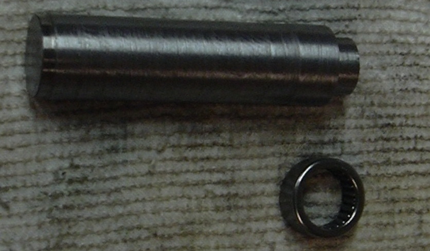
Cam needle bearing diver, yeah you can hammer them in with just about any old chunk of steel. But, I've seen the little rollers get knocked out, this tool keeps the rollers in place and when the tool bottoms out on the case you know the bearing is flush.
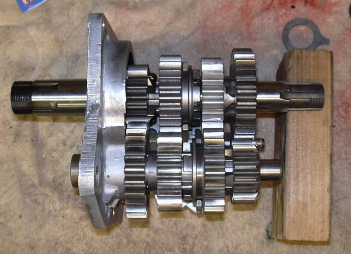
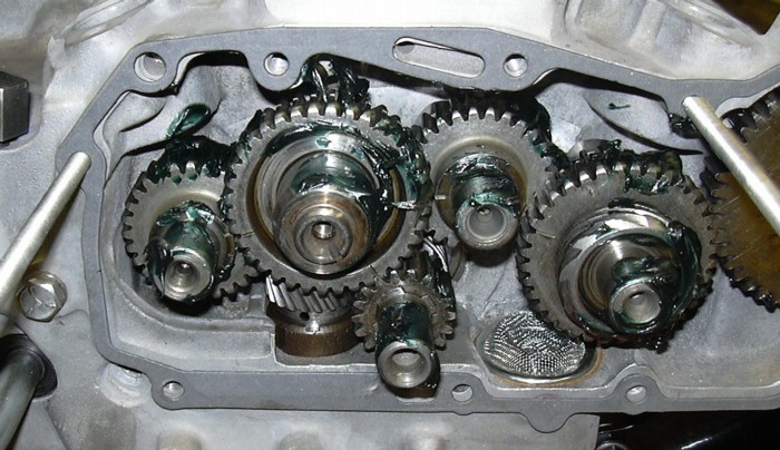
On to the tranny, this tranny was built up from the leftovers of a dozen basket cases. And god damn, it went together just fine. I did have to replace the clutch gear and the main shaft third gear, but that was about it. The gear cluster was stuffed into the crankcase a dozen times to get the shaft end play set just right, but that is about par for the course. I keep a good assortment of main and counter shaft shims on hand to set end play.
The main shaft bearing race had to be replaced, I used a Jim's race this time and found that it was sized just right so that a set of standard size rollers fit just fine after the race was pressed in. Some of the races I've used required extensive honing to achieve a good fit for the rollers. The last remaining problem is that the 1st/2nd shifter fork tain't quite long enough, it goes into first too far and not quite far enough into second. A plus .020" fork is on order. It always pisses me off, I've got 6 shifter forks laying around and I never have the size I need. So the shifter fork is keeping me from finalizing the tranny installation. If you look closely at the lower shaft (the counter shaft) you can see that there is no clearance between the counter shaft low gear (1st gear) and the sliding gear (counter shaft 3rd gear) and too much clearance between the sliding gear (counter shaft 3rd) and counter shaft 2nd gear.
What next? I can never quite predict where a day in the shop will lead. So with the cams and tranny waiting for yet more parts I decide to look at the oil tank. I picked up an XLCH tank on eBay for 10 bucks, I always thought those square CH tanks were all the same. Guess what? They ain't. Least this one ain't. I was missing the mounting brackets so I bought a set from J&P, figuring the tank would be a simple bolt in. Wrong. I don't know what the hell them brackets fit but they sure as hell don't fit this tank. So an hour with a hacksaw and 14 trips to the bench grinder and now the brackets fit the tank. Neither the tank nor the brackets will ever be the same. While I was at it I decided I didn't like that flange on the oil tank, it makes the tank look like it was pressed together with a fork like a pie crust so I ground flange all off and am in the process of welding the seam back together. It'll be one of a kind. That should be finished up and maybe even powder coated by tomorrow.
Progress to date, Monday, April 10, 2006. It was a tough fight, but I won. The oil tank is bolted in. Maybe permanently. We'll see. I was expecting to have to cut the lower oil tank mounting bracket to get it to clear the Pingle motor mount. As it turns out the Pingle mount, being thicker than the stock mount, also moved the lower oil tank mount up so that the oil tank wanted to run into the top frame tube. I wasn't expecting to have to redesign and re-fabricate the tank mounts. Nothing that a day of grinding, cutting, welding, grinding, drilling, cutting, grinding, welding, trimming, test fitting, grinding, welding, cutting, test fitting, drilling, welding, etc., etc. couldn't fix. And of course I ran out of argon for my TIG and had to finish up with good old oxy/acetylene. My shop is more like a blacksmith forge on days like that. Like I said, it was a tough fight but I won. The oil tank is fitted the way I like. That standing flange around the middle was cut off and the seam was re-welded. I plugged all the holes on the tank and pressure tested it with about 8 PSI of air and soapy water. One weld had a pin-hole in it that I had to redo. To those of you who have changed the oil on 70s XLCHs, you know how conveniently the tank drain plug is located, wedged in right between the battery tray and the primary cover. I stole an idea from late model XLs; the drain plug was drilled and tapped for a ⅛" NPT by ⅜" hose barb and a hunk of hose attached and run down along side the primary so I can drain the oil without making a big mess. The hose will be plugged with a ⅜" bolt. The sludge in the tank was flushed out in my parts washer, two bottles of CLR managed to dissolve most all the rust. I managed to get the tank, mounting brackets, kick start lever and gear shift lever powder coated today and bolted them in just as soon as they were cooled off enough to handle. That is it for now. I'll be waiting for the plus .020" shifter fork and cam cover pinion bushing to arrive, then I can finish up the tranny and cams. In the meantime, the blackness is beginning to show.
Progress to date, Monday, April 17, 2006. Some more parts from J&P arrived last week including the +.020 shifter fork and the pinion bushing and a few other odds and ends. I took a day trip to Chicago on Saturday to visit my son. Allow me to digress and talk about the singularly most stupid bit of motorcycle riding I have ever seen in my life which I witnessed in Chicago on Saturday. I was in Evanston heading back to O'Hare traveling south on the Edens when a group of six sport bike riders merged onto the expressway, rather than doing the customary sport bike 140 MPH these jokers were doing 30 MPH. "What's up with that I thought?" I soon found out, the rear three riders would block traffic while the front three would hammer the throttle and do the customary roll on wheelies. Cool. They did this routine a few times, really pissing me off as I lugged along behind them at 30 MPH on a 65 MPH expressway. But the really stupid part hadn't happened yet. Apparently one of the lead dumb assholes dropped something and the dumb asshole bringing up the rear of the stupid parade came, are you ready for this, to a complete kickstand down stop in the middle of the Edens to pick up whatever dumb asshole rider number one dropped. Needless to say, amidst the smell of burning rubber and sound of squealing brakes, there were a lot of pissed off motorist besides me. Way to go dickheads.
Which brings me to Easter Sunday. I spent Easter Sunday, the way I like, out in the shop doing motorcycle things. The +.020 shifter fork fixed the first/second gear engagement problem. So bolting the tranny in was a no brainer? Wrong. The tranny, which basically shifted OK on the bench didn't shift worth a damn when bolted into the crank case. How could this be? Well, I'll tell you. The end of the shifter shaft was hitting the pawl carrier and binding up. I stuck the shifter shaft on my lathe and made it a few thou shorter. Mind you this was a brand new shifter shaft. The moral of the story is that you can never assume that any two given parts will fit together properly. Everything must be checked and double checked. Everything. I bet I had this tranny bolted in 15 times before I was satisfied that it was good to go.
The new pinion bushing inside diameter was too small to fit over the end of the pinion shaft, I sort of expected this. I took it over to my lathe and turned about .004" out of the I.D. to get a good fit on the pinion shaft. It is easier to this before you press it into the cam cover. After that I drilled all the cam bushings for the anti-rotation pin, I did this on a plain old drill press. Then I checked each cam's fit in the bushings one more time. After that I checked each cams end play one at a time by installing the cam and bolting down the cam cover and reaching in through the lifter block hole with a screw driver and pushing the cam back and forth. According to the HD service manual you are supposed to be able to stick a feeler gage in the hole to measure the end play. Yeah right, this is one operation I do by feel only. A little too much end play ain't going to hurt anything, not enough and the motor won't turn over. Anyway I check all four cams one at a time. The cam cover gasket must be the one you are planning on using, different thickness of gaskets will change the cam end play. Remember too much won't hurt, not enough motor won't spin. To keep the gasket lined up while I am taking the cover off and on I used a couple ¼" threaded rods to hold the gasket in position.
So after all that dorking around with bushings and bearings and end play it is finally time to install and time the cams and bolt the cover down. So here are the cams covered with grease and all of the mystical marks lined up. I use grease for assembly lube because it might be six months until this engine is fired up and I think the oil will drain off of the parts and leave them high and dry whereas grease will stick and still be where you need it to be even if it takes a year until the motor is fired.
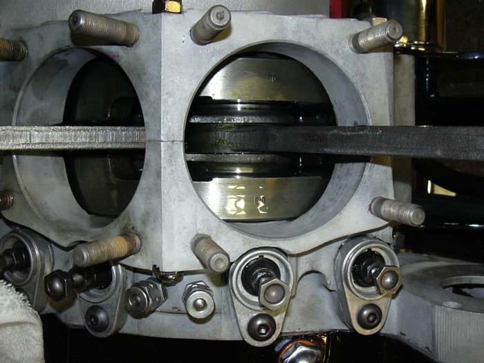
So put the cam cover on and tighten the bolts and once again make sure the motor spins freely. If it don't, you fucked up, take it apart and figure out what is binding it up. Now, one of my special checks. I hook up the oil pump supply line and fill it with engine oil, sometimes a funnel stuck in the end of a hose is all you need, in this case I hooked it right up to the oil tank. Then I grab the rods and spin the motor over until oil wells up in the holes that go to the rocker boxes. This makes sure that the pump is working and that all the oil passages are free and clear. Sometimes it is hard to make a new motor start pumping oil, in those cases I put an air hose on the oil tank and pressurize the tank with maybe three or four PSI out of my air hose to force oil into the supply line. I had to do that on this motor. It is not unusual. After oil wells up into those rocker box supply holes, I plug them. I usually just stick an old ball bearing in the fitting for the rocker supply line. Then keep spinning the motor, after just a little bit you should see oil coming out from around the connecting rods. If you don't you've got a problem. And as bad as it is to find that out now, it is a lot better to fine out now than after you've fired and fried the engine. All the oil you see around these rods is oil that got there by me spinning the engine over just by grabbing the ends of the connecting rods. I also dumped a little oil into the cam chest through the lifter block holes, after just a little spinning oil started being pumped out of the return to the tank fitting, so now I know the scavenge side of the pump is also working. I do this procedure on every engine I have the heads and barrels off on. It is cheap insurance to avoid costly problems down the road. And now a short story, I used to work in a Triumph shop years ago. A guy brought a bike in that he had rebuilt, but it ran shitty and he was wanting us professionals to do a professional type tune up on it. Well, I happened to draw the work order and took said motorcycle for a test ride and, god damn the guy was right, it ran like shit; missed, farted and would barely do 30 MPH. I wheeled the bike into the shop and up onto my stand, got my strobe light out and was going to check the timing. I started it up and it ran for 30 seconds, emitted a loud squeal and proceeded to lock up tighter than a drum. The would-be rebuilder had crossed the supply and return oil lines thus starving the new engine of oil. It wasn't pretty. I always make sure the oil pump aactually pumps and circulates oil before the engine is started the first. Enough said?
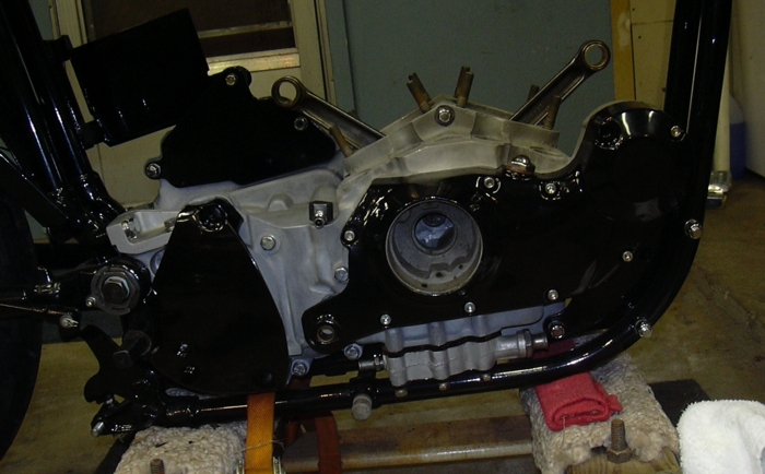
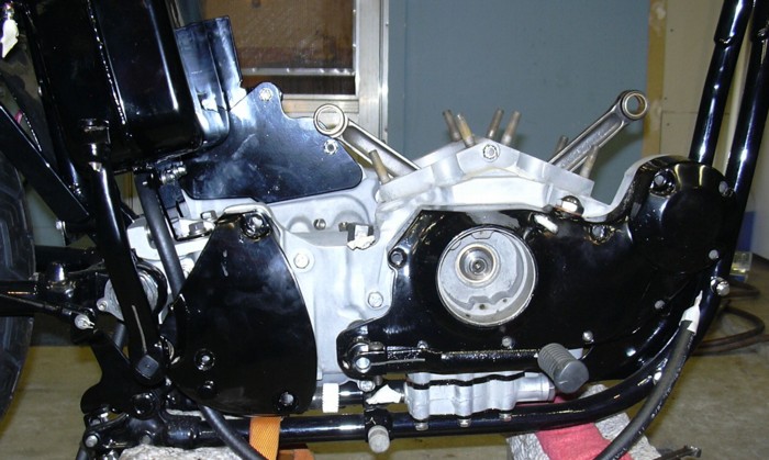
So this is the quitting point for now. The lifter blocks are bolted in. The oil lines are all hooked up. I have an external filter and a cooler installed, both leftovers from other projects. The motor is all closed up, cept for them two big holes on the top. I wonder what goes there? I need to order the big nut for the drive sprocket, could have sworn I had one of those laying around somewhere, but I sure as hell can't find it now. I also need to order a primary chain. I think I managed to round up all the clutch parts I'll need over the last couple of months on eBay, so I should be able to put the primary together. I also need to order some .010" over piston rings. I have a set of used pistons that were mated once upon a time to the jugs I'm planning on using. It is actually starting to look like a motorcycle. I think I can see some light at the end of the tunnel.... So let's wrap up Chapter 5 and move on to Chapter 6.