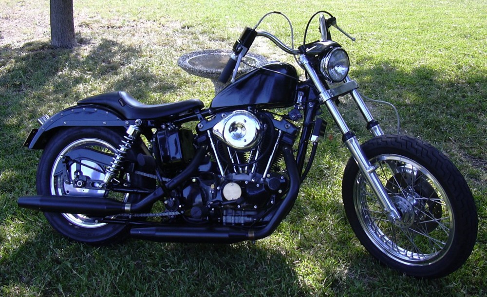
Progress to date, Monday, May 15, 2006. Well let's see... Exhaust pipes. Yeah, that's the ticket. So I had a couple of sets of beat up old drag pipes and some big ol' mufflers off a Softtail. Being the socially responsible guy that I am I decided to use mufflers on this project. Oh muffler cores??? Cores, we don't need no stinking muffler cores. So a bunch of cutting and a little welding and the Softtail mufflers fit right on. The only problem being the chrome on the beat up old drag pipes is all fucked up. So, being as the theme of the bike is all black, I decided to get me some of that high temp powder and coat the exhaust. The high temp powder has a satin finish.
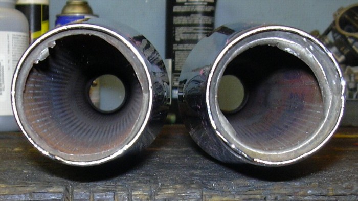
Anyway they look like mufflers...
The die cast air cleaner came in, I just had to drill one hole in the backing plate for the carb brace. Always brace the carb, no matter what kind of clamps you use the carb will loosen and the intake will start leaking. Always brace the carb. Just about any old hunk of steel strap will work.
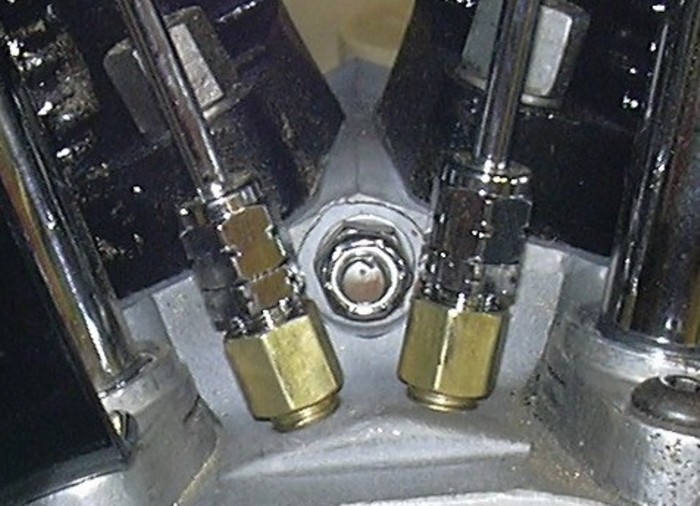
The rocker box oil feeder lines also came in, and god dammit, you'd think those would be a couple of parts that are pretty easy for our Chinese friends to make cheap copies of. But, dammit, I've bought several sets of those over the last couple of years and the god damn tubes are a 1/4 inch too short. Do you hear that you Chinese manufacturer of cheap knock off parts? Buy yourselves a new fucking ruler and learn how to use it and start making the god damn tubes ¼" longer. Until that happens you'll need to get a ⅛" NPT male to female extension to make up for the fact that the damn tube is too short.
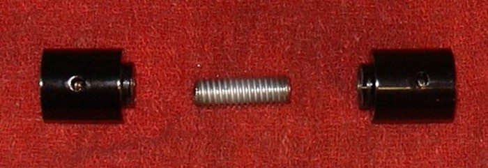
The gas tank came in also, I powder coated it too. It does not have the finish quality of a good paint job, but powder coat is cheap and durable. I put heli-coils in the rear tank mounting hole so I can use button heads stainless bolts instead of the through bolt. I also made a couple of bushings for the front tank mount that are threaded internally, the bushings have shoulders on them to keep them centered in the hole drilled in the frame casting and are held together with a little hunk of threaded rod. Now I can use stainless button head bolts on the front mount too. I did all this because it is a pain in the ass to stuff a through bolt through the coil mount, tank mount lugs and spacers. The bushings take the place of the spacers and are fixed to the frame, making it a whole bunch easier to get the front bolts for the tank installed.
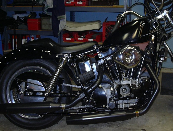
So this is it so far.
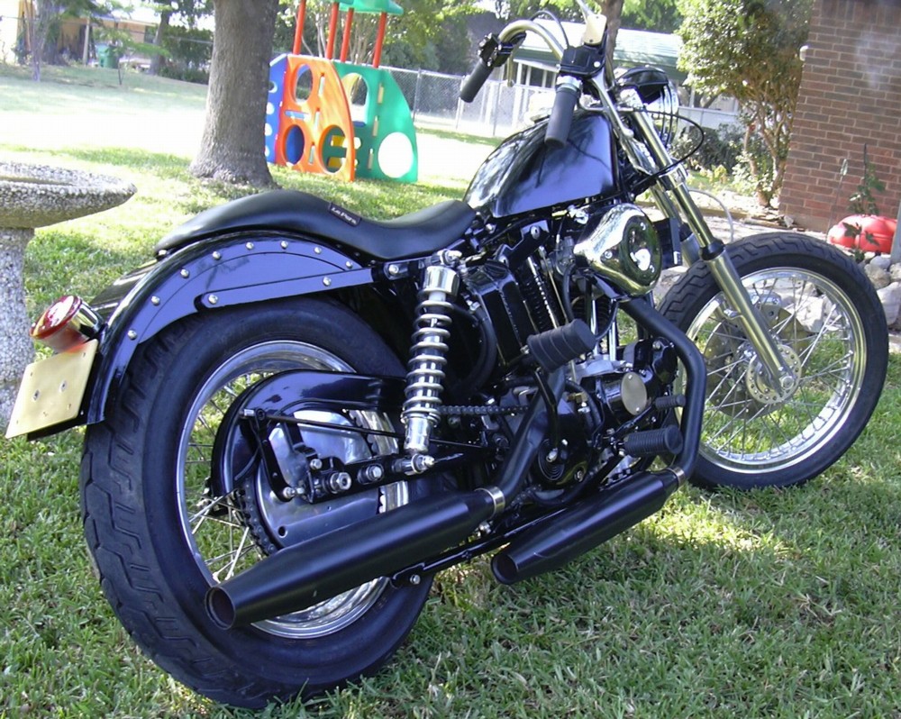
Progress to date, Friday, May 19, 2006. Over the last couple of days I've started taking care of a bunch of little stuff, like chain adjustment, tightening the rear wheel axle, brake adjustment, clutch adjustment etc. A couple of words on a couple of things. Clutch adjustment is a two step process, first you adjust the cable. Back the cable adjuster out just about all the way, screw the adjuster on the primary cover in all the way, this fully releases the clutch. Now use the cable adjuster and take all the slack out of the cable, leave just a gnat's ass of free play in the cable. And that would be a tiny gnat's ass. You want the cable to be just barely loaded. Now, tighten the cable adjuster jamb nut. The cable is adjusted, don't fuck with it any more. Second part is the free play adjustment, back out the clutch adjuster on the primary until it is completely loose, now turn it in until there is just a slight amount of free play at the clutch lever. Tighten the jamb nut on the adjuster screw and you are done. You should be able to put the bike in gear, pull in the clutch and roll the bike back and forth, it should roll freely. If you can't roll the bike without feeling the clutch drag, repeat the adjustment process. If you still can't roll the bike freely while it is in gear after re-doing the adjustment your spring spacers are too short or your springs are adjusted too tight (on those clutches that don't use the spacers). Pull the primary off and get the longer spacers (different length spacers used to be available, you may be able to find them) or put a washer on each stud. If your washers are too thick, the clutch will slip. Oh course you won't find that out until everything is back together and you've driven the bike. Yeah, I know it is a pain in the ass. The Sportster clutch sucks when compared to old Flathead clutches or old Panhead clutches for a couple of reasons. On those bikes the kick start drove through the clutch, if a clutch didn't slip while you were kicking, generally it would hold while you were driving. So you didn't have to put the whole thing together and drive it only to find out that the clutch slipped. On a Sportster the kick start drives through the clutch basket, not through the clutch plates, so when you kick the engine over you are not even using the clutch. Plus, on the old Pans and Flatheads you could pop the derby cover off the primary and adjust the clutch springs in about 2 minutes. No need to disassemble the primary.
Rear wheel, chain and brake adjustment. I like to keep the rear chain a little on the loose side. Your chain adjustment changes as the swing arm bounces up and down. If the swing arm pivot was exactly in line with the drive sprocket the adjustment would stay the same. But it isn't. So as the swing arm bounces up and down the effect is to make the chain a little shorter with each bounce. Anyway a chain that is too tight will put excessive loading on the trans main shaft bearing and could cause that bearing to fail. So I keep my chain a little on the loose side. So, after you have the chain adjusted and the wheel centered you can cinch down the rear axle nut. Next is the brake adjustment. The first step is to center the shoes in the drum, unfortunately people often skip this step, which is really too bad because it does help what is a crappy brake to begin with work a lot better. Loosen the shoe pivot stud, that would be the bolt on the front side of the brake, the one the anchors the brake in the slot in the swing arm. Now put a wrench on the brake actuator arm nut and apply the brake as hard as you can. The shoe pivot stud mounting hole is a little bigger than the stud, when you apply the brake with the shoe pivot bolt loosened, you center the shoes in the drum thus maximizing the contact area between the shoes and the drum and correspondingly increasing the efficiency of the brake. While applying the brake, tighten the shoe pivot stud bolt. Next you adjust the brake peddle height, that is that bolt on the brake crossover shaft, a lot of bikes I've seen are missing that adjustment bolt. Turn the bolt to move the peddle up or down, set it where you like it. And finally, the brake peddle free play is set with that nut on the end of the brake rod. Set it so that the brake does not drag and there is just a little movement before the brake starts to grab.
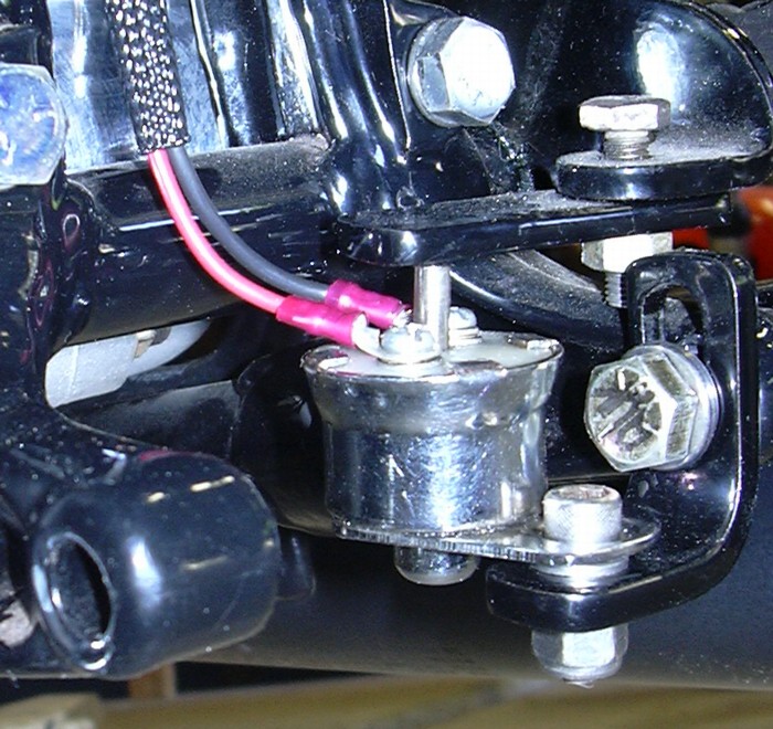
I like to hide the brake light switch under the frame, if you ask me a switch hanging from the swing arm hooked to the brake rod with a spring really looks like crap. I bolt mine to the frame and use a chunk of steel bolted to the crossover shaft to actuate the switch. I also wire mine backwards from most people. Usually people wire the switch to be normally open, when you step on the brake, you pull on a spring that pulls on the switch and closes the contacts. I use a switch that is normally closed, the actuator keeps the switch open (brake light off) until you step on the brake, then the actuator moves away from the switch and the contacts close (brake light on). It works for me.
And, lastly for now, the lines for the front brake came in last week, I got them hooked up and bled out the brake. This one bled out pretty easy. I usually use a pump oil can filled with brake fluid and hose connected to the bleeder screw to fill the master cylinder from the bottom up. But this time I just filled the master cylinder and used the conventional technique and it worked fine, didn't even make a mess.
One more thing, I bought some different shocks on eBay a couple of weeks ago, they finally came. I swapped the springs from those shocks onto the shocks I already had to fix my mushy spring problem. The new springs work good, nice and firm.
One more thing, I sat down and ordered what will hopefully be my last load of stuff from J&P. I've got wiring to do and timing to set and then... Will it run???
Progress to date, Saturday, May 20, 2006. Time to start thinking about electricity. Generators from hell. Generally speaking, if a generator will run as motor when hooked up to a battery it will also generate electricity. I have two old generators the idea being to resurrect one, no sweat right? So I took one, hooked the “A” terminal up to the positive battery post, grounded the field and hooked it up to the negative, tried to motor it and of course nothing happened. Then again I didn't really expect anything would happen, although it would have been nice if something did happen. Specifically, it would have been nice if the generator motored, on the other hand, it didn't melt down or go up in flames. What to do? Try another generator of course, hooked it up and tried to motor it. Well in the back of my mind I must have known that it wouldn't work either, and, so as not to disappoint me, the generator obliged by not working. This one also managed not to go up in a ball of flames either. So at least no parts were destroyed beyond repair.
Well, I took both of them apart to see what kind of shape they were in, neither one of them looked too bad on the inside and one actually looked liked it had a reconditioned armature in it and fairly new field coils. Whoever cut the segments on the armature slipped and cut an extra groove partway through a segment, the armature looked like it should still work though. Oh yeah, one of the field coils was a little loose on the shoe. I took one generator, cleaned it, up put it back together and tried it again. Still nothing. I tried it with the armature out of the other one, nope, still nada. Checked continuity of the coils, they were OK, replaced a questionable splice between the coils, try again, still nada. Hmmmm. Cleaned up the other generator, put it back together, tried motoring it, nope, still nada. Tried it with the armature from the other generator, you guessed it, nada.
Well it was time to more accurately reproduce the configuration of an operating generator. I could bolt one of these generators to one of my other bikes, but that’s a lot of work. But I needed an engine to spin the generators for further troubleshooting. An engine, or a motor, well my lathe is a motor. It was easy to clamp the generators in a drill press vise bolted to the cross slide, couple the input shaft to the lathe chuck with a piece of stiff rubber hose (to make up for any misalignment.) Hook up a regulator, battery and electrical load (head light) with alligator clips and presto the bikes electrical system is reproduced. Now I can take my volt-ohm meter and make some measurements to track down what is going wrong.
Now test spin both generators and find out they are actually putting out negative voltage. How can that be? Well I had flashed the field to establish the correct polarity way back when I started messing with this project, so that wasn't the problem. Now I began swapping field coils, field shoes, armatures, generator frames and brush assemblies in every conceivable combination. Nothing works. I spend 12 hours swapping parts around, all with no help and each time cleaning things up carefully, checking the connections and looking for anything that might not be quite right. It all looks good, yet it don’t work. I start checking parts catalogs for how much a new generator costs, I find out it is more than I want to spend. Besides that, I’ve got two generators, both with seemingly good parts. I ought to be able to make one good one or I ain’t a mechanic. This is starting to piss me off.
Harley generators are not complicated pieces of machinery. An armature rotates between two soft iron shoes that are wrapped with the fine wire comprising the field coils. The soft iron shoes retain some residual magnetism to get the ball rolling, then as the coils of wire on the armature pass through the magnetic field of the field shoes an electric current is generated in the armature, the current is then conducted from the rotating armature to the rest of the motorcycle’s electrical system through the brushes. The current is regulated by controlling the strength of the magnetic field in the field shoes, a job that falls to the voltage regulator. One down and dirty test for an HD generator is to bypass the regulator by grounding the field. Harley generators don’t put out a helluva lot of juice to begin with so it is usually safe to bypass the voltage regulator by grounding the field, just don’t rev the engine up or you'll blow the light bulbs. Not much to the system. Pretty much 8th grade science class theory. So here I am, all seemingly good parts, but no goddamn electricity.
As much as I hate to, I’m buying a new one with a built in regulator.
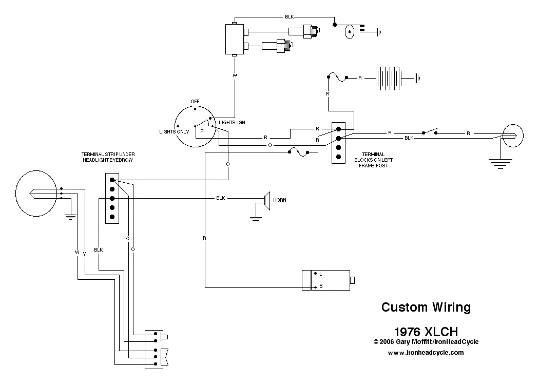
So after I get the generator how will this bike be wired up? I think I have here a diagram for using just about the absolute minimum wiring for a street legal XL in Texas. In Texas you have to have a high/low beam and a horn and, of course, a brake light. The generator with the built-in regulator gets rid of the regulator and associated wiring, so that cleans things up quite a bit too.
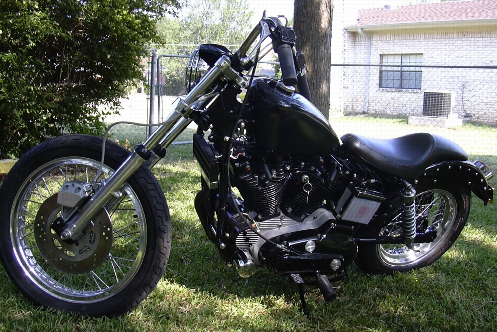
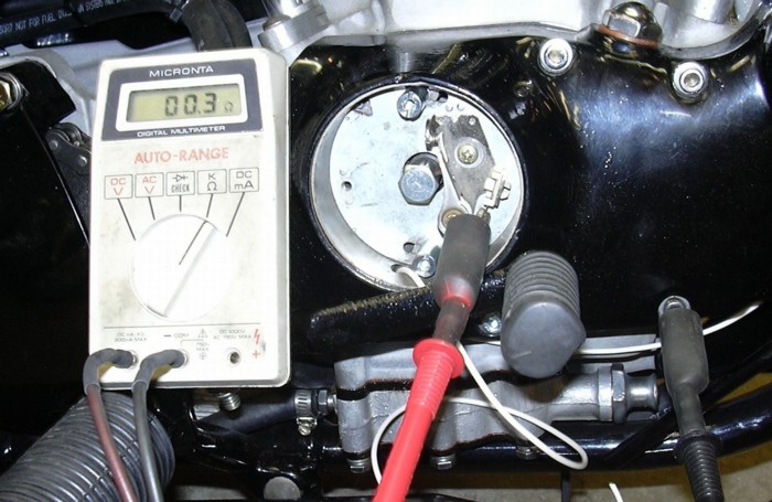
Progress to date, Wednesday, May 24, 2006. What hopefully will be the last box of goodies from J&P Cycles arrived yesterday. So I went about bolting the goodies on. The point mounting plate studs also came, so I set the points and timing. The point plate came out of a bike I was working on a couple of years ago, it had new points and a new condenser bolted to it. Believe it or not I did not have to re-adjust the point gap. It was good to go as is. I used an ohm meter to check for the point opening and used the ohm meter to statically set the engine timing. This method works best if the coil wire and condenser are disconnected. You also have to rotate the point cam against the advance mechanism to get the cam into the full advance position.
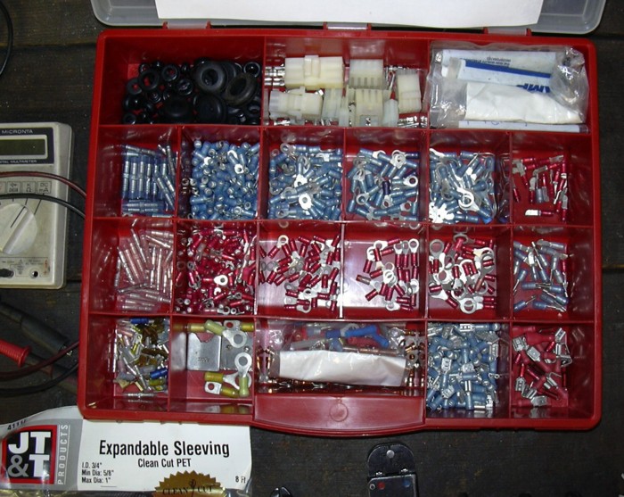
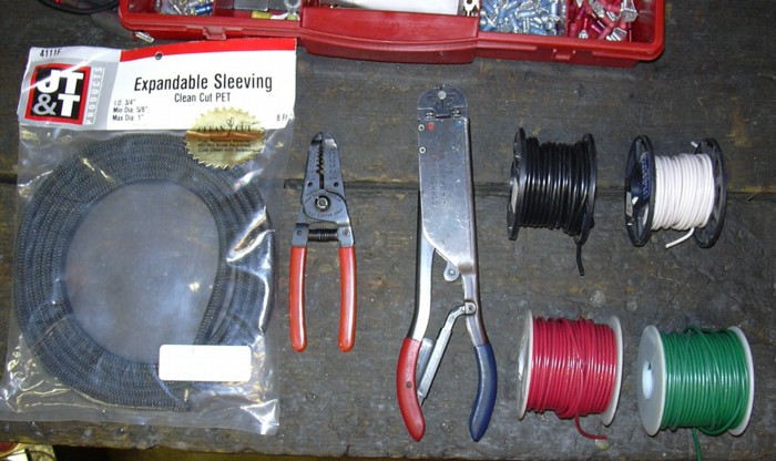
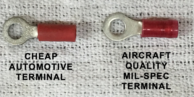
So now it is on to wiring, which means I'm going to do a little more preaching. I use only aircraft type mil spec crimp connectors. If you look closely at the typical crimp connector bought at an auto parts store you will see that the crimp barrel is split down the middle, you will also notice that there is no provision incorporated for strain relief for the wire. The aircraft type crimps are known as restricted entry PIDG (pre insulated diamond grip), the barrels are not split, hence the connector will not split down the middle when it is crimped. Secondly the crimpers are calibrated (certification of calibration required when used on aircraft) so as to crimp the wire sufficiently tight so that the wire will break before it pulls out of the connector. The connector also has a thin metal shell which is designed to crimp around the insulation of the wire to support the wire and thus relieve the strain on the conductor. The "restricted entry" part of the name means that the connector is sized so that the insulated part of the wire can not be inserted into the part of the conductor that is supposed to grip the bare wire. I bought the crimper used years ago up at the Osh Kosh airshow, I think it was about 70 bucks. Kind of expensive but I have probably crimped thousands of connectors with it. The crimp connectors themselves cost about 20 cents each, I get them from an outfit called Mouser Electronics. Also kind of expensive, but cheap when compared to the hassle of a broken wire at 3 AM on a country road in the middle of nowhere. In case I haven't made myself clear, them automotive type connectors you crimp with a pliers like device are junk of the worst kind. Avoid them at all costs. Now let me bitch about soldier joints, they also suck. Soldier wicks up the wire and makes it stiff, thus making it more likely to break. Soldier also corrodes and work hardens. Nonetheless there are a few instances where you have to use it, like when wiring handlebar switches. I also use something called "snake skin" to sleeve the wire bundles. This stuff is a woven sleeve, it keeps the wires together and offers some protection against abrasion. I use a lighter to fuse the ends of the snake skin sleeving to keep it from unraveling.
Also in the box of goodies was the petcock, so I screwed it into the bottom of the tank and bolted the tank down for keeps... after I finished running the wiring. There was also a battery in the box, battery hold down strap and battery top. All I need to do is run the battery down to the local lawn mower shop to be filled up with acid. The new built in regulator generator was also in the box along with a generator drive gear. Unfortunately the drive gear fits so loose on the generator shaft so as to be useless. Right now I am trying to hunt up a new source for the drive gear. This gear happens to be a V-Twin part, generally I'm usually satisfied with V-Twin stuff, but this gear is junk.
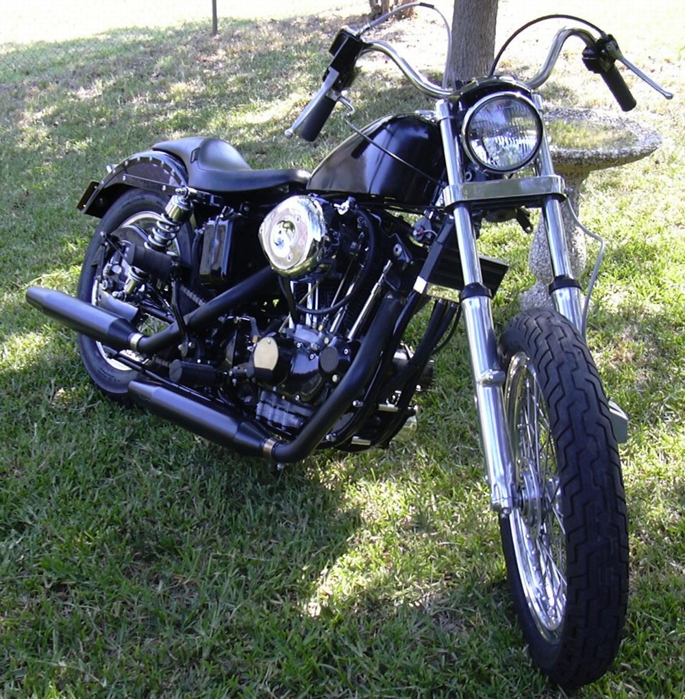
Right now all I have left to do is weld a little crack in the headlight eyebrow, mount the headlight, mount the battery and put gas in it.
Progress to date, Tuesday, June 13, 2006. Miss me? Wondering where I've been? I've been looking for generator drive gears. Remember my previous bitch on how the V-Twin gear from J&P was looser than a crack whore on Saturday night in front of a pile of rock? Well maybe those weren't my exact words. In any case I called my Local HD dealer wondering if per chance he maybe had a NOS HD gear sitting on the shelf. Of course not, but that is the answer I expected. The friendly parts girl volunteered to special order me an aftermarket one since the HD gear is obsolete. She guaranteed the aftermarket gear she would get would be a high quality made in the good old USA part. The gear came in a week later. Guess what? Same piece of Taiwanese crap I already had. I asked her if HD had a computer system with which she could query other HD dealers to see if another dealer had a NOS genuine HD gear sitting on a shelf and have it shipped over. The nice parts girl made a few calls and found a supposedly NOS HD gear at another dealer. A few days later gear number three arrived. It came in a sealed plastic bag with no markings whatsoever. It was maybe a little tighter than the previous two gears but still basically as loose as a crack whore on Saturday night in front of a pile of rock. I stopped at a chopper shop and the guy had a used drive gear, make that gear number four. I bought it. It was possibly usable. I took one more look at eBay and finally found a guy selling a NOS HD drive gear. I won the auction and few days later the gear showed up in a sealed HD plastic bag. My hands trembling with anticipation, I opened the bag and tried it on my new 300 dollar plus generator with built in regulator... and... success!!! I went from gears looser than a crack whore to one tighter than a nun. Finally, on the fifth try, I found a good gear. At last I was able to bolt a gear to the generator and plug that big hole in the side of the engine. That all happened two days ago. Why was the drive gear such a big deal? I put together a lot of generators and never really paid much attention to the drive gear and I probably wouldn't have this time. Except... that my new 300 dollar plus change generator has a big warning in the box that the two year warranty would be null and void if the armature was damaged by a loose fitting drive gear. I wasn't about to fuck up a 300 dollar part by putting a bad gear on it.
So that was the last stumbling block. I hooked up the battery, hooked up the generator, put gas in the tank and kicked it over and kicked it over and kicked it a few more times. Nothing, not a damn fart, nothing. I pulled the plugs and checked for spark, yep, plenty of spark. I pulled the air cleaner and checked for gas, no gas. None. I pulled the float bowl, dry... How can that be? The float was grossly out of adjustment that's how. Adjusted the float, put the carb back together, kicked... and she fired right up. Ran crappy as all get out. Did a little tweaking on the carb and got it running a little better and took it for a drive around the block.
Not bad. The carb will need some work, jetting. But not bad. The tranny shifted fine, the clutch worked great, no oil leaks, the rods and pistons stayed attached to the flywheels, the brakes worked, the high temp powder didn't melt off the pipers. Really not too bad for the first ride. I like it. So I am calling this project done. I will probably get a front fender eventually, if you've ever driven a bike without one in rain or through a puddle, you know why. And the carb will need some more tweaking. But stick a fork in it and turn it over, it's done.