How to Build a Sportster
(from a pile of junk)
The full sized version of pictures on this website can be viewed by right clicking on the picture and selecting "VIEW IMAGE", then use your browser back button to return to the web page.
Chapter Four
Progress to date, Sunday, February 26, 2006. Time to start talking about the engine. The heart and soul of a Sportster lives in the engine. And despite a long hard life, this one ain't dead yet.
This engine came to me in trade for some work I did I while back. Before I even knew I was going to start this project (which is why I don't have any "before" pictures) I tore the engine down just to see how bad it was. It was pretty bad. The trans and primary, including the clutch, were missing completely along with the cams and lifters. When this thing finally gave up the ghost the old owner stripped it of everything that might be usable, so he thought. The rod bearings and crankpin were junk. One of the jugs was junk, the piston pin clip had come out and the piston pin started sawing a groove in the cylinder wall. And then there was the infamous hole in the crankcase referenced back in Chapter 1. All things considered, I've got to think that this engine proves how tough a Harley engine can be. It ran, for a while at least, with little or no oil pressure or flow, the crankpin had ruts in it 1/16” deep and the rear jug must have had no compression whatsoever. Yet it ran, for awhile, without catastrophic failure. It must have been knocking like a sonuvabitch and it couldn't have had much power, but the rods stayed in the crankcase and the pistons stayed attached to the rods. No easy task when you look at the abuse it suffered.
So why even bother trying to resurrect this piece of crap? On the surface it looks like it would cost a fortune. And, indeed, it would cost most people a fortune. But I have some machining capability, can bore my own cylinders, cut my own valve seats and valves and heli-arc the crankcase. Plus I have a ton, literally, of parts lying around. Extra heads, jugs, tranny gears, shafts etc. So I should be able to pick the best of the leftovers and make a decent engine. And then there is eBay for everything else. I try to keep a step ahead as far as hunting up parts is concerned. I found some cams back in December that I know I won't be needing for weeks and right now I am looking for a clutch I won't actually be needing for weeks or months.
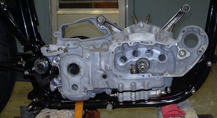
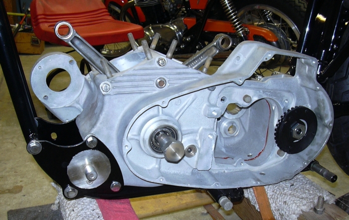
So back to the specifics of this motor. I pulled it apart last summer and started cleaning it up. Once the sprocket cover was off the hole in the crankcase was obvious. The missing pieces were obvious once the primary and cam cover were pulled. I was hoping some of the guts would still be inside, but the engine had been picked clean. The trashed jug was obvious once the head was pulled off. The rods had an ⅛" vertical play in them, so the trashed crankpin was also obvious once the barrels were pulled off. Nonetheless, to really see what was going on, this sadly abused piece of dirty, filthy, oil encrusted crud needed to be thoroughly cleaned up. So, despite the obvious temptation just to heave it into a dumpster, I began the cleanup. The cases were split, the flywheels pulled and split. A couple of cans of gunk and plenty of water were used to get the worst of the dirt and grime off. Then a trip to the sandblaster revitalized the cases, and, you know, it started to look not so bad. There was no other damage (besides the hole) to the cases. Very often you will find cracks around the main bearing boss. These cases actually looked pretty good. So it became obvious that a little welding would salvage the cases and at the very least I'd have a set of usable cases out of the deal.
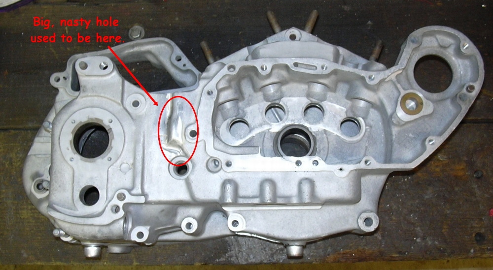
So let's move on to the hole and how to repair it. Unfortunately, I didn't take any before repair pictures, so you'll just have to believe me when I say it was very nasty. Apparently this bike threw the drive chain, or maybe a rock got jammed between the chain and the crankcase. In any case, something had punched a hole in the crankcase just forward of the drive sprocket and just above where the gearshift shaft comes through the case. The hole did not go all the way through the case but only into the oil passageway that feeds the pump. Apparently somebody tried a real half assed repair job. The hole was covered with weld splatter, a real mess. I guess that somebody laid the bike on its side and tried to weld it without cleaning any crud off and with out draining the oil. This was a burned, soot encrusted, splattery mess. The only thing to do was to get out a Dremel tool and grind all the bad metal out, so the hole kept getting bigger and bigger. But it had to be, because the only way to heli-arc is if everything is perfectly clean with solid metal to weld to. So once all the bad metal was dug out, I machined an aluminum bar to be the same diameter as the damaged oil passageway. I stuck the aluminum bar into the passageway, of course it plugged the passageway, but it gave me something to weld on. Then, after some more localized cleaning, I began welding. I laid several passes over the bar I had filled the passageway with, thus building the weldment up to the level of the surrounding metal. Then using the Dremel tool, I shaped and blended the weldment into the surrounding metal. After bead blasting to further blend the texture of the finished weld, this repair job will be invisible to the naked eye. After all that was done, it was a simple matter to drill my filler bar out of the oil passageway to restore the flow path back to the oil pump. Fortunately, this passage is short enough and wide enough that you can visually inspect its entire length to ensure it is clean and free of any defects. So the next step will be the final clean up and inspection of the crankcases.
The trashed rod bearings, were due, I assume, to the big hole in the crankcase oil passage that let all the oil leak out, thus cavitating the oil pump I'm sure. Rod bearings don't like to be run without oil.
Progress to date, Monday, February 27, 2006 . The crankcases got their final cleanup today, if I had a set of rods and flywheels ready to go, I could have put the engine together. Which is why fitting rod bearings will be the second topic today. But, back to crankcase cleaning. These cases have been degreased, soaked in soap and water, degreased, soaked in soap and water again, sandblasted, blown out with compressed air, sandblasted some more, more soap and water, blown out with air again, one more soap and water cycle and blown out with compressed air again. Overkill? Maybe, maybe not. I've seen a couple of engines destroyed because sandblast grit was not completely cleaned out. In addition to all that every threaded hole had a tap run down through it until it bottomed out. Every threaded hole had all the crud picked out of the bottom with a pick. I may be a little paranoid, but I have see threaded holes destroyed by crud trapped in the bottom of the hole. One of two things usually happens, especially on the primary cover holes. Pieces of old gasket goop and old gasket get pushed into the bottom of the hole. This junk reaches a point where it cannot be compressed any farther, well the screw and the crud cannot occupy the same area. The screw bottoms out on the crud, yet the hamfist installing the screw notices the screw hasn't yet bottomed on the primary cover. The solution? More force. Either (1) the threads will strip out or (2) the screw hole blows out (cracks) the crankcase. I'm serious. I ain't making this up. I have seen several engines where the threaded primary screw holes have longitudinally split. So take an extra 15 minutes and make sure all, and I mean all the crud, is dug out of the screw hole before jamming a screw in. I am not going to powder coat these cases. I like bare aluminum cases.
Let's talk about fitting rod bearings in specific and measuring in general, neither of which is a completely an exact science. So why is this relative to the problem at hand of fitting rod bearings to this XL? Let's examine the problem. Having picked the best of my leftover crankpins and the best of my leftover rod assemblies I need to fit bearings. Not a problem… if I worked at an HD dealer and had a parts bin full of the various oversizes of rod roller bearings or if I had a rod bearing lapping tool. (I now have the lapping tool and routinely lap rod races to the next oversize. From a machinist point of view it is enjoyable, if not messy work.) I simply start with standard size bearings and move up in oversizes until the best fit is achieved or I lap the rod races bigger until the best fit is achieved. I don't have those options. I don't have the lapping tool and I don't have a parts department full of rod bearings in the various oversizes. (I now keep at least one set of standard and oversize bearings in stock, I can probably lap your rod races and have them on the way back to you in 24 hours.) I need to measure everything very carefully and order the size I need, that fits, the first time. So what's the problem? Take your measurements and make your calculations and order the damn bearings. OK. So let's see what happens. My micrometer set came with a gage block that is supposed to be 1.000” inches long. So I use that to adjust my micrometer and set it to 1.000”, whenever I set the test gage block in the micrometer it measures 1.000” because I adjusted the micrometer to that test gage block. So lets put that test gage block in my vernier dial indicator, uh oh it measures just a scooch over 1.000”. Probably about 1.0005”. Now let's put that same test gage block in my digital read out vernier caliper, now it reads .999”. So which is correct? Well I hope the micrometer is, but that all depends on the test gage block. In my previous life as Director of Maintenance at a general aviation fixed base of operation (FBO) all of our measuring instruments had to have a certificate of calibration traceable back to the Bureau of Weights and Standards. This was required by the FAA, that way when I measured an airplane piston and cylinder and determined the clearance to be too large I could prove it by the calibration certificate of my measuring instrument. No such requirement for calibrating measuring instruments exists in the world of motorcycle maintenance. So common sense would dictate that shops and individuals such as myself have their measuring instruments calibrated. But, in fact, most shops do not. I know this because I have worked at several shops over the years and I never saw a certificate of calibration at any of them. I do not have my instruments calibrated at a lab, I probably should, but I don't because calibration costs money. In lieu of laboratory calibration I use gage blocks to test my indicators and calipers. So, for purposes of this exercise I will assume that the 1.000” gage block is accurate and that my vernier dial indicator and vernier digital indicator are off and that the gage block is correct. I paid good money for the micrometer set and I am relying on the manufacturer to provide me with a product equal in quality to the money I spent.
But what does all this have to do with connecting rods? Well to save some money on this project I carefully inspected all my leftover rod sets looking for the best set of rods and the best crankpin. And by carefully I mean using a magnifying glass to inspect the pin and rod races for unacceptable wear and using a micrometer to check for out of round. Having found an acceptable crankpin and acceptable rod set I need to order a bearing set that will fit the first time. So I need to measure accurately so that I can order the right size bearings, the first time.
So how do you calculate the bearing size? Well it ain't rocket science, but like so many other things mechanical it does take at least a half a brain and decent tools. First off, measure the crankpin diameter. In my case the crankpin mics out to 1.2480”. Then measure the inside diameter of the rod races. Use a telescope gage and then measure the length of the telescope gage. In my case the rod races mic out to 1.6265”. Then subtract the pin diameter from the race diameter and you end up with .3785. Now you need to factor in the desired running clearance that is about .001”. So subtract .001” from .3785 and that will leave you with .3775”. Now divide that number by 2 and you will end up with the desired diameter of the rollers. So the desired roller diameter in this case is .1887. A standard roller is .1875” so I need a roller that is .0012” oversize. Got all that?
Connecting rod big end inside diameter |
1.6265” |
From which subtract the crankpin diameter |
- 1.2480” |
The result = |
.3785” |
Now subtract the desired running clearance |
-.0010” |
The result = |
.3775” |
Divide that by 2 to get desired roller size = |
.1887” |
Subtract standard roller diameter to get oversize |
-.1875” |
Desired oversize = |
.0012” |
Closest available oversize = |
.0010” |
As it happens I have a set of standard size rollers, at least the digital readout vernier caliper would have me believe they are standard size, and they felt a little loose when I test fit them so a .001” oversize should be just about right. So that is what I will order and hopefully they will fit just right. Actually I decided to hedge my bet a little. I also decided to order a set of .0008” oversize rollers, just in case I was off a little.
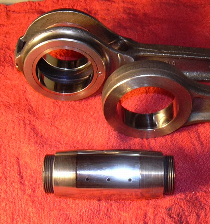
Finally, these are the rods I've decided to use. I found this set in my dumpster diving a couple of months ago. No nicks or scratches on the bearing surfaces, out of round by less than .001, I think they will be just fine. I had contemplated buying a set of new S&S rods, but $300.00 plus gets to be a chunk of change and this set looks damn good. A word to the wise, there are other "stock" rod sets sold in the various catalogs. Those rods sell for about $100.00 less than the S&S rods and I think they are made in China. I bought a set once and tried to use them. I could not true the flywheels with those rods installed, the best I could get them down to was about .006" out of round, that is way to much for a crank assembly. I think the tapers were cut wrong. I sent them back and will never buy a set of rods that are not genuine HD or S&S. (Since originally written, HD rods have gone obsolete and are no longer available. The only quality option is S&S and since I don't see them listed on the S&S website anymore, they may also be obsolete. Some versions are available from some suppliers and MSRP is well over $400.00. If you have HD rods, hang on to them. I also have the tooling now for replacing the rod races.)
Progress to date, Sunday, March 12, 2006. Well the last couple of days have been busy. The rod rollers, pinion rollers, main bearings and motor mount have all shown up. which means that I can put the crankcase together and put the crankcase in the frame. I prefer to put the engine in the frame with just the wheels in it. It is lighter and easier to maneuver so you have less chance of fucking up the frame. Everything outside of the flywheels can be easily installed on the engine while it is sitting in the frame. But, I get ahead of myself, let's back up a bit and start over. I test fit the bearings to the crankpin and the rods, I ended up using the .001" oversize. Now, knowing that the bearings fit the crankpin and the rods OK, the next step was to begin assembling the flywheels. The brass thrust washers on these wheels were all fucked up from chunks of the old bearing being drug past them as the bearing disintegrated. The thing that is good about these thrust washers is that you can take them out and turn them around and reuse them. You have to get a Dremel tool and grind out the areas where they were peened in position. But that is not hard and it also helps to drill a small hole right where the washer and the flywheel intersect so you can get a small pick under the washer to pry it out. Once you get it out you have to carefully clean the recess the washer drops into so that there is a good flush fit, you also need to make sure the old metal that was peened over is completely ground out because that metal will interfere with the washer sitting flush. Once the recess is cleaned and you have a nice flush fit with the turned around washer you are ready to peen the new one into position. I have found that the washer likes to pop out when you peen the flywheel to stake the washer in place. I use a C-clap to hold the washer flush while I do my peening.
After the washers are reinstalled it is time to start bolting up the flywheels. I start with the pinion side. This is your last chance to make sure the hollow pinion shaft is not blocked, blow it out one more time. Just for good measure I squirt some carb cleaner down the shaft and make sure it comes out the hole in the flywheel. This is the oil feed to the rod bearings. It must be free and clear. Now blow out the crankpin one more time and squirt some carb cleaner through it. Put the key on the pin and drop it into the hole, put the big nut on and tighten it to 150 foot/pounds. One may ask, how do you hold onto something that is round and tighten it to 150 foot/pounds? Easy, you drop the flywheel over your hand made jig that you have clamped up in your vise. (Since this was originally written I've acquired a Rowe flywheel holding fixture, and I'm glad I did, because the company that made that fixture, Rowe USA Corporation, closed in 2013. Rebuilding engines like this is fast becoming a lost art. When you develop a rod knock on your Evo motor, the mechanic at the Harley dealer will sell you an entire flywheel/rod set... for $2000.00...)
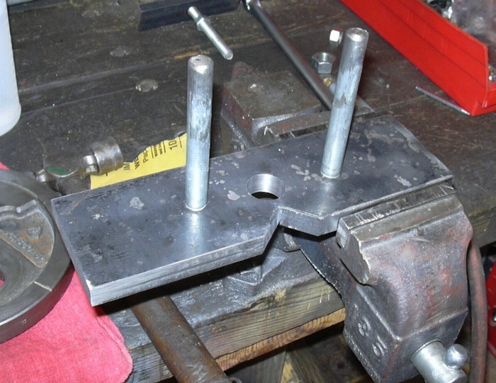
Not at all an elegant tool, but it does the job.
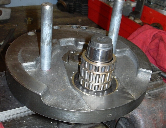
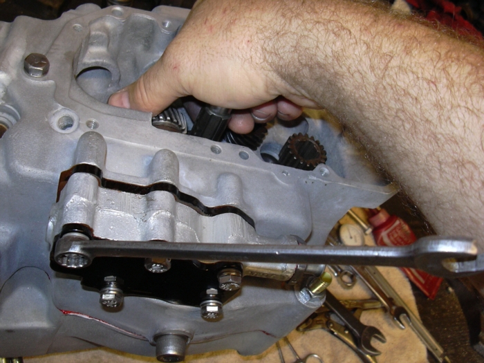
This is the crankpin torqued up with the rollers waiting for rods to be slipped over. I slobber the rollers up with grease to hold them in place, other wise the bastards go falling all over the place.
Now all you have to do is drop the rods on and the other flywheel and torque it up. I use a couple of steel channels connected with a 1/2" threaded rod to hold the flywheels in rough alignment while I snug the last crankpin nut. Then with the nut snug I haul the rods to my lathe and chuck the assembly up between a couple of centers to check the run out. Usually the steel channel routine gets them damn close and a couple of whacks with a brass hammer will get them down to the less than the .002" limit per the HD manual. Then it is back over to the holding fixture to tighten the last nut to the 150 foot/pound torque. By the way, I do use a calibrated torque wrench. I also use Loctite on the threads of the big nuts. And, words of caution and warning, the tapers on the pin must be absolutely clean, no oil, no grease, no anti-seize, no Loctite. Absolutely clean, I wipe them down with rubbing alcohol and blow them with air just before the final assembly.
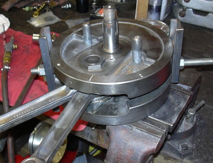
Another hand made tool, this one to keep the flywheels from shifting when you tighten the big nuts...
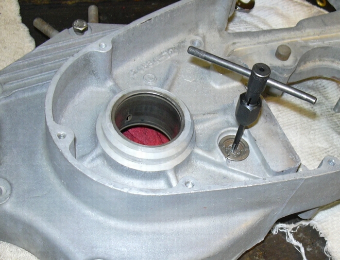
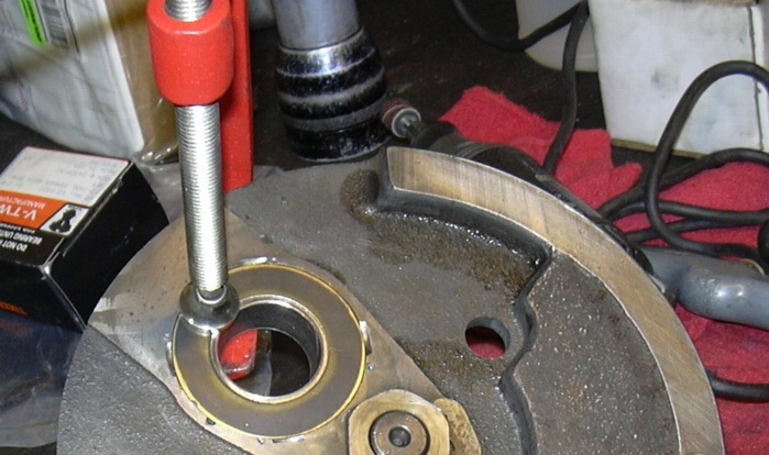
Tapping the oil transfer hole so it can be plugged with a 6-32 screw...
So, now it is time for final prep on the crankcases before assembly. They've been cleaned and cleaned again, the nasty hole has been welded up and all the threaded bolt holes have been chased with a tap. Two last steps remain. I plug the hole in the oil transfer valve. As near as I can figure the damn oil transfer valve doesn't do anything good. What it will do is allow engine oil to fill the primary and trans. So if you've ever wondered how your three quart oil system can hold 6 quarts, that would be after the bike has been sitting for 3 months and all the oil in the tank has leaked past the pressure check valve and filled the crankcase and then leaked through the oil transfer valve and filled the primary and trans. I drill and tap the valve for a 6-32 screw and Loctite the screw into the hole. Engine oil stays in the engine and trans oil stays in the trans.
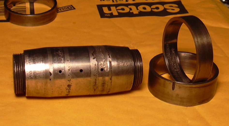
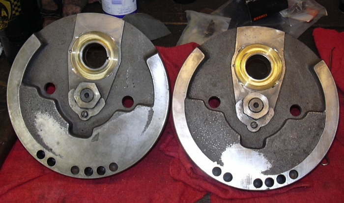
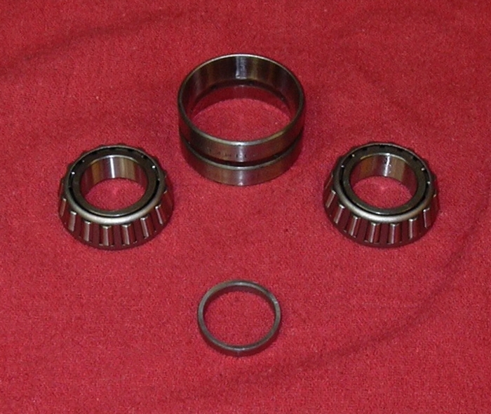
The final step is to press in the main bearing double race. A word about the XL main bearing set up. What you see in the picture are the two bearings, the double race and the spacer that goes between them. At your local bearing house I have found that you can buy the bearings, you can buy the race. But, you can't buy the spacer or the matched set. And they are a matched set. If you use a spacer that is too small the rollers will be smashed onto the double race when you tighten the big nut on the sprocket shaft and the bearing will fail; if the spacer is too big there will be too much end play on your crankshaft and the flywheel will hit the crankcase and the bearing will fail. Theoretically, you can buy the race and the bearings and then make your own spacer, but it is so much easier just to buy the set. (I have run across engines with no spacer installed and the wrong spacer installed. I have acquired an assortment of spacers over the years and I now have a small fixture for checking the bearing end play.)
And with the bearing installed, the crankcase halves are ready to be bolted together. Which leads me to talk about gasket sealers. On perfectly smooth and true metal surfaces sealers and gaskets need not be used as the metal faces will be in 100% contact with each other thus allowing no pathway for oil to migrate between mated surfaces. Of course no surface is perfectly smooth or true and there are lots of pathways for oil to migrate between mated surfaces. Harley crankcases are no exception. I use Loctite gasket maker, it is an anaerobic sealer, meaning that it only cures when it is tightly pressed between the surfaces it is sealing. There are a couple of advantages to this, it won't cure until it is bolted up, so you have plenty of time to work with it. Secondly, and perhaps most importantly, the sealer that oozes out when the parts are tightened up will never cure. This means that hardened lumps of sealer will never jamb up your delicate oil pump drive gears and break them. It also means hardened lumps of sealer will never clog up the small oil passages in your crankpin, starving your rod bearings of oil and causing catastrophic engine failure. For the record, I do not recommend silicone sealer, nor do I ever use silicone sealers anywhere on any motorcycle engine I assemble. Silicone will do both of the bad things I've just described. Furthermore, silicone swells and eventually dissolves in gasoline, a substance commonly found around most gasoline powered engines. Additionally, silicone is difficult to squeeze out from between mating surfaces, so what happens in some cases is that there is no metal to metal contact between parts. While this may be OK for an automobile valve cover, it is not OK for a highly stressed crankcase. Eventually the silicone will be unable to bear the load between the cases and it will disintegrate; this will cause the case bolts to loose torque, the cases will loosen up, leak and chafe against each other.
I know there are skeptics out there. So I have some anecdotal proof. I used to mechanic on small airplanes. Well a guy brought a Mooney into the shop with a cylinder base leaking, again, and he needed it fixed, again, somebody had previously repaired a leak in the same area. For those of you who aren't familiar, a small airplane engine cylinder is bolted to a crankcase much the same way a cylinder is bolted to your Harley crankcase, it is sealed with an o-ring that is wedged into a chamfer on the crankcase when the cylinder flange is bolted down. The cylinder enjoys metal to metal contact with the crankcase and all the horsepower that cylinder produces is contained by the mounting bolts, some of which double as through studs that hold the crankcases together. Well on this particular engine the o-ring had gotten hard and started to leak oil, the cylinder needed to be completely removed and the o-ring replaced. However the previous mechanic had tried to avoid the rather big job of pulling the jug completely off to replace the o-ring, rather he had merely loosened it and squirted silicone sealer into the gap and tightened it all back up. Well, tight as he got it, it weren't quite tight enough, that silicone did flatten out and it did stop the leak… temporarily. It also left a thin little silicone gasket, maybe only .001” thick between the cylinder and the crankcase. Well now the cylinder didn't enjoy that metal to metal contact with the crankcase and all the horsepower the cylinder was producing was being transmitted through that thin layer of silicone. Before too long the silicone was torn up, and oil was leaking out again. And you know what else happened, when that silicone was eaten away the bolts and studs holding down the cylinder started to loose torque, the cylinder started to chafe against the crankcase. The crankcase was ruined. A few hundred dollar repair job turned into a $7000.00 engine overhaul, oh yeah, that didn't include the $5000.00 core charge that had to be paid because the core wasn't any good, what with them ruined cases and all. I never use silicone on critical engine surfaces.
I know some of you are also saying, “Hey dumbass, my brandy new Harley has a bead of silicone oozing out of the crankcase parting surface right now.” All I can say is that you and I don't know just exactly what kind of silicone was used or exactly what kind of process Harley uses to apply it. For me, the Loctite works great, I've put a whole bunch of engines together with it (Harley, BSA, Triumph, Yamaha, Honda) and none of them ever leaked. For me silicone ain't worth the risk, I don't use it. Period.
Enough lecture about silicone, time to put the crank cases together. Lay the left case on the primary side, put some grease on the sprocket shaft bearing, set the wheels in place, lay down a bead of Loctite Gasket Eliminator, plop the right case on top and bolt it up. Flip the motor over, insert the bearing spacer over the sprocket shaft and then the outer Timken sprocket shaft bearing, squeeze the bearing onto the shaft with the sprocket shaft nut. Flip the motor back over to the primary side and insert your pinion shaft rollers and cage, grease them up real good first. Make one more check of your free-plays and make sure the motor turns over nice and smooth, if it don't you done something wrong, take it all back apart and start over. Piece of cake.
Well that was a bunch of work. Time for a beer. Then I'll bolt the engine into the frame. Oops, almost forgot. Always put the oil pump on first. You can't install the oil pump once the engine is bolted down. I keep saying that one of these days I am going to design a bolt-in frame section so you can remove the oil pump without unbolting the engine. Well today ain't one of these days. So I best put the oil pump in first. You tain't heard enough about gasket sealer yet. The oil pump uses thin paper gaskets, it also has a bunch of little passageways that are best not full of gasket goop and those little gears will break if a gob of hardened silicone is run through them. The best thing I have found to use on oil pump gaskets is that spray on copper gasket sealant. You get a nice even coat, no gobs to clog passages or break gears. And, last word on the pump. Tighten the mounting bolts evenly. Spin the pump with your fingers as you tighten it. If the pump gets stiff or binds up gently tap it with a plastic hammer until it loosens up. The pump must turn freely.
OK, let's bolt the engine in the frame now. Oops almost forgot. Do yourself a favor here, install the damn kick start shaft too, before you bolt the engine in the frame. While it is possible to install the shaft with the engine installed, that god damn rubber seal is a real pain in the ass to do with the engine bolted in the frame. I have found that the squared rubber seal they are selling these days doesn't seem to be cut the right size. It is damn near impossible to install that seal even with the engine on the bench. I have taken to using two o-rings back to back in the seal recess, they work just fine and are a whole bunch easier to get in.
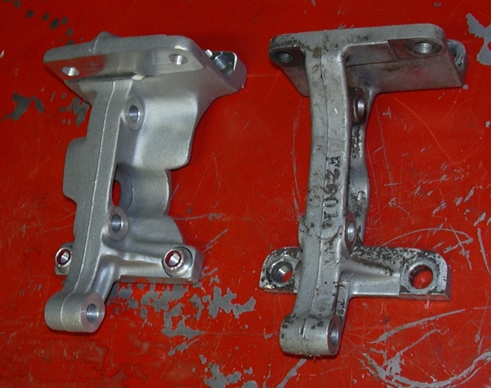
OK, so now let's bolt the engine in. Not quite, let's talk about the rear motor mount first. The HD mount sucks. Everyone I've ever seen is cracked. Every one. If you think yours ain't cracked, that's only because you haven't looked at it close enough yet. The other thing that sucks about the HD mount is that you have to split the crankcases to replace it. Those are the reasons why I always install the Pingle rear engine mount. It can be removed and installed without splitting the crankcase, and it is like twice as thick as the HD mount. If you have a cracked HD mount and you don't want to split your cases to replace it, you can go after it with a ¼" drill bit and weaken it enough by drilling a bunch of holes in it so that a couple of whacks with a hammer and chisel will break it right off, seriously, that works. A caution about installing the rear mount, lightly bolt just the mount to the frame before you bolt it to the engine. Check all four mount points and ensure there are no gaps, if there are make yourself some shims to fill the gap. I think one of the reasons the HD mount cracks is because they don't always fit flat on the frame and tightening them without being flat stresses them and leads to an eventual crack.
So now it OK to install the motor. Tighten the rear mounts first, then the front. See, all done...
So on to Chapter 5, top end, tranny, clutch, primary, what to do next???